3MAINTENANCE__O.pdf - 第88页
2.2 Selection of P . C . B . Flow Direction ( L / R ) s ) Setup Operation of P . C . B . Transfer Section P . C . B . Transfer Section for “ L R ” R S i d e [ L S i d e ] A • Lever B ■ E • Spring A ( Large Wire Diameter …
2.2
Selection
of
P
.
C
.
B
.
Flow
Direction
(
L
/
R
)
(
3
)
Precautionary
Items
in
Setting
of
Device
Offset
Data
The
devices
and
offset
parameters
adjusted
and
set
for
both
“
L
R
”
and
“
R
L
”
directions
.
Do
not
change
them
unless
necessary
.
factory
-
are
A
CAUTION
In
the
following
cases
,
the
offset
between
the
feed
claw
and
a
P
.
C
.
B
.
must
be
adjusted
.
•
In
the
case
of
“
Outline
Reference
”
,
the
end
plane
of
P
.
C
.
B
.
is
not
aligned
correctly
with
the
end
plane
of
the
outline
pilot
pin
when
the
P
.
C
.
B
.
transfer
is
located
at
its
transfer
limit
.
•
In
the
case
of
“
Hole
Reference
”
,
Pilot
Pin
PI
(
reference
side
)
does
not
match
the
slit
on
the
P
.
C
.
B
.
when
the
P
.
C
.
B
.
transfer
is
located
at
its
transfer
limit
.
•
The
offset
data
is
cleared
for
an
unaccountable
reason
.
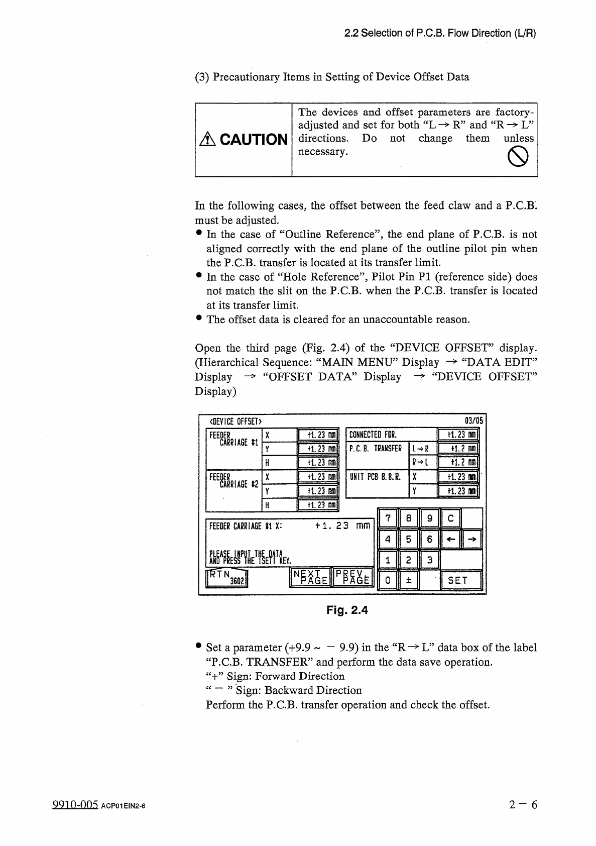
Open
the
third
page
(
Fig
.
2.4
)
of
the
“
DEVICE
OFFSET
”
display
.
“
DATA
EDIT
”
£
DEVICE
OFFSET
”
(
Hierarchical
Sequence
:
“
MAIN
MENU
”
Display
Display
—
“
OFFSET
DATA
”
Display
Display
)
03
/
05
〈
DEVICE
OFFSET
)
ft
.
23
m
CONNECTED
FDR
.
tl
.
23
m
F
1
舰
X
#
1
P
.
C
.
B
.
TRANSFER
H
.
2
m
fi
.
23
m
L
—
R
Y
R
—
L
n
,
2
m
十
1.23
lam
H
fl
.
23
in
UNIT
PCB
B
.
8
.
R
.
X
争
1.23
no
n
.
23
m
争
1.23
(
W
Y
H
.
23
m
H
7
8
9
C
十
1
.
23
_
FEEDER
CARRIAGE
111
X
:
5
6
4
2
3
1
IFQl
N
0
SET
±
Fig
.
2.4
#
Set
a
parameter
(
+
9.9
一
9.9
)
in
the
“
R
—
L
”
data
box
of
the
label
“
P
.
C
.
B
.
TRANSFER
”
and
perform
the
data
save
operation
.
“
十
”
Sign
:
Forward
Direction
“
一
”
Sign
:
Perform
the
P
.
C
.
B
.
transfer
operation
and
check
the
offset
.
Backward
Direction
99
in
-
nn
5
2
—
6
ACP
01
EIN
2
-
6
2.2
Selection
of
P
.
C
.
B
.
Flow
Direction
(
L
/
R
)
s
)
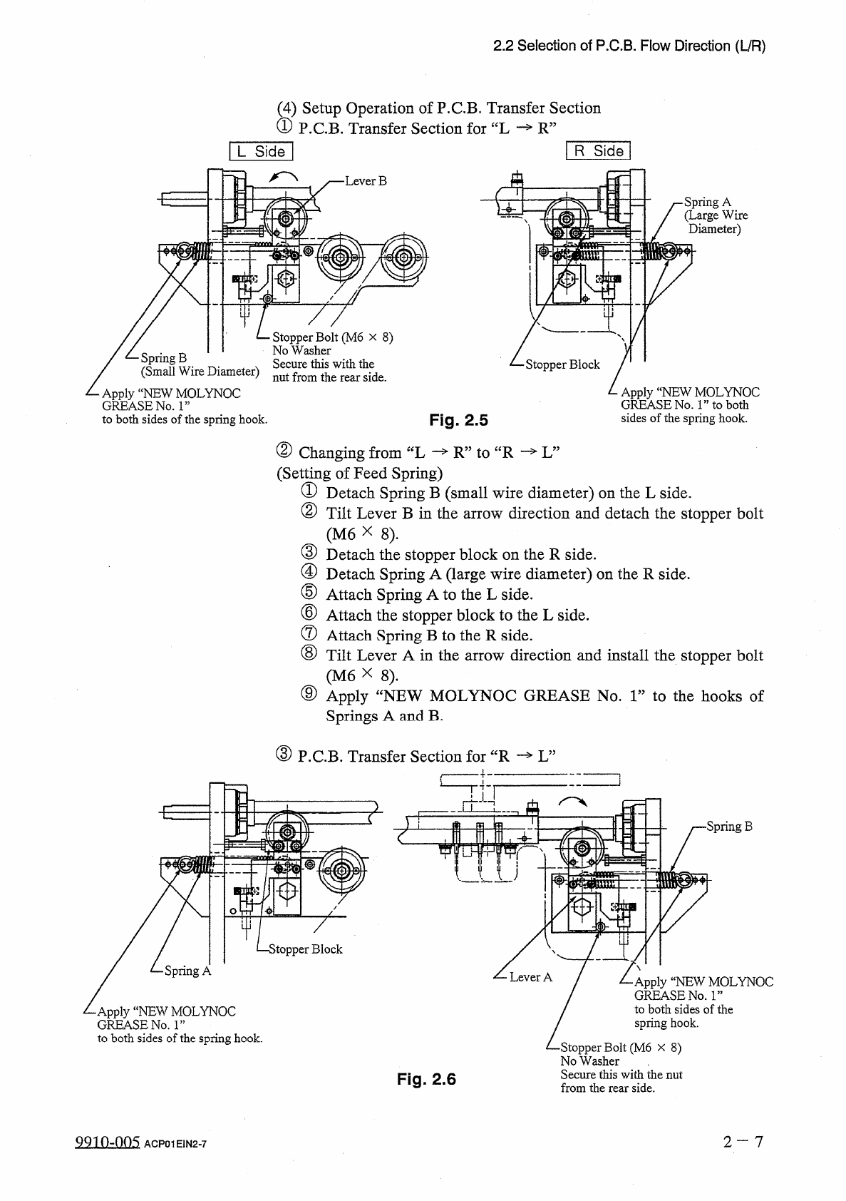
Setup
Operation
of
P
.
C
.
B
.
Transfer
Section
P
.
C
.
B
.
Transfer
Section
for
“
L
R
”
R
Side
[
L
Side
]
A
•
Lever
B
■
E
•
Spring
A
(
Large
Wire
Diameter
)
I
中
Stopper
Bolt
(
M
6
x
8
)
No
Washer
Secure
this
with
the
nut
from
the
rear
side
.
/
乙
Spring
B
/
(
Small
Wire
Diameter
)
Apply
“
NEW
MOLYNOC
GREASE
No
.
1
”
to
both
sides
of
the
spring
hook
.
Stopper
Block
Apply
“
NEW
MOLYNOC
GREASE
No
.
1
”
to
both
sides
of
the
spring
hook
.
Fig
.
2.5
②
Changing
from
“
L
(
Setting
of
Feed
Spring
)
①
Detach
Spring
B
(
small
wire
diameter
)
on
the
L
side
.
②
Tilt
Lever
B
in
the
arrow
direction
and
detach
the
stopper
bolt
(
M
6
X
8
)
.
③
Detach
the
stopper
block
on
the
R
side
.
④
Detach
Spring
A
(
large
wire
diameter
)
on
the
R
side
.
⑤
Attach
Spring
A
to
the
L
side
.
⑥
Attach
the
stopper
block
to
the
L
side
.
⑦
Attach
Spring
B
to
the
R
side
.
⑧
Tilt
Lever
A
in
the
arrow
direction
and
install
the
stopper
bolt
(
M
6
X
8
)
.
⑨
Apply
Springs
A
and
B
.
—
R
”
to
“
R
—
L
”
fNEW
MOLYNOC
GREASE
No
.
1
”
to
the
hooks
of
③
P
.
C
.
B
.
Transfer
Section
for
“
R
—
L
”
£
■
Spring
B
>
topper
Block
Spring
A
Apply
“
NEW
MOLYNOC
GREASE
No
.
ls
,
to
both
sides
of
the
spring
hook
.
•
Apply
“
NEW
MOLYNOC
GREASE
No
.
1
”
to
both
sides
of
the
spring
hook
.
•
Stopper
Bolt
(
M
6
x
8
)
No
Washer
Secure
this
with
the
nut
from
the
rear
side
.
Fig
.
2.6
2
—
7
QQ
10.005
ACP
01
EIN
2
-
7
Ohupter
S
Page
3.1
Hierarchical
Structure
of
Special
Selection
Displays
3
-
1
3
-
2
3.2
“
SPECIAL
SEL
.
”
Display
3.3
Manual
Nozzle
Bypass
1
3.4
Device
Test
3
-
4
3
-
5
3
-
6
3.4
.
1
X
/
Y
Table
Test
3.4
.
2
P
.
E
.
C
.
Recognition
Test
3.4
.
3
Component
Recognition
Test
-
3.5
Offset
Teaching
3.5
.
1
Head
*
Nozzle
Offset
Teaching
…
'
3.5
.
2
Head
Origin
Offset
Teaching
•
…
.
3.5
.
3
Master
Head
Offset
Teaching
…
1
3.5
.
4
P
.
E
.
C
.
Camera
Offset
Teaching
3.5
.
5
Component
Recognition
Camera
Offset
Teaching
3
-
9
3
-
13
3
-
21
3
-
23
3
-
32
3
-
35
3
-
38
3
-
41
3
-
43
3.6
Device
Check
3
-
44
3.6
.
1
Input
Check
3.6
.
2
Machine
Program
Information
3.7
Unit
Adjustment
3.7
.
1
Feeder
Unit
3
-
52
3
-
53
3
-
54
3
-
55
3.7
.
2
Nozzle
Adjustment
3.7
.
3
Camera
Position
Adjustment
3.8
HDD
/
FDD
Operation
3.8
.
1
Pattern
Program
3.8
.
2
Saving
the
All
Backup
Data
-
3.8
.
3
Recall
Messages
3.8
.
4
Offset
Data
,
Device
Data
,
Placement
Head
/
Nozzle
Data
,
Nozzle
Data
…
3
-
6 4
-
7
3
-
64
-
10
3
-
57
3
-
59
3
-
60
3
-
63
3.8
.
5
Component
Library
(
All
)
3.8
.
6
Component
Library
(
Each
)
3.8
.
7
Pattern
Program
Management
Data
3.8
.
8
Management
Data
3.8
.
9
Bypass
&
Rate
Data
3.9
Setting
of
Maintenance
Warning
Mode
•
3
-
64
-
12
3
-
64
-
15
3
-
64
-
18
3
-
64
-
21
3
-
65
9910
-
004
ACP
01
EINCC
3