3MAINTENANCE__O.pdf - 第82页
2.1 Sensitivity Adjustment of Unit P . C . B . B . B . R . Detection Photosensor 2.1 Sensitivity Adjustment of Unit P . C . B . B . B . R . Detection Photosensor ( 1 ) Purpose of Sensitivity Adjustment When the unit P . …
©
tepter
1
Page
2.1
Sensitivity
Adjustment
of
Unit
P
.
C
.
B
.
B
.
B
.
R
.
Detection
Photosensor
2.2
Selection
of
P
.
C
.
B
.
Flow
Direction
(
L
/
R
)
2
-
1
2
-
4
9910
-
005
ACP
01
E
1
NCC
2
2.1
Sensitivity
Adjustment
of
Unit
P
.
C
.
B
.
B
.
B
.
R
.
Detection
Photosensor
2.1
Sensitivity
Adjustment
of
Unit
P
.
C
.
B
.
B
.
B
.
R
.
Detection
Photosensor
(
1
)
Purpose
of
Sensitivity
Adjustment
When
the
unit
P
.
C
.
B
.
B
.
B
.
R
.
detection
function
is
used
,
be
sure
to
adjust
the
amplifier
sensitivity
of
this
photosensor
.
Remarks
:
The
external
rotary
switch
allows
4
kinds
of
sensitivities
of
the
B
.
B
.
R
.
detection
photosensor
to
be
set
and
stored
in
memory
and
each
stored
sensivitity
can
be
selected
whenever
necessary
.
(
Valid
Setting
:
“
0
”
(
zero
)
through
“
3
”
)
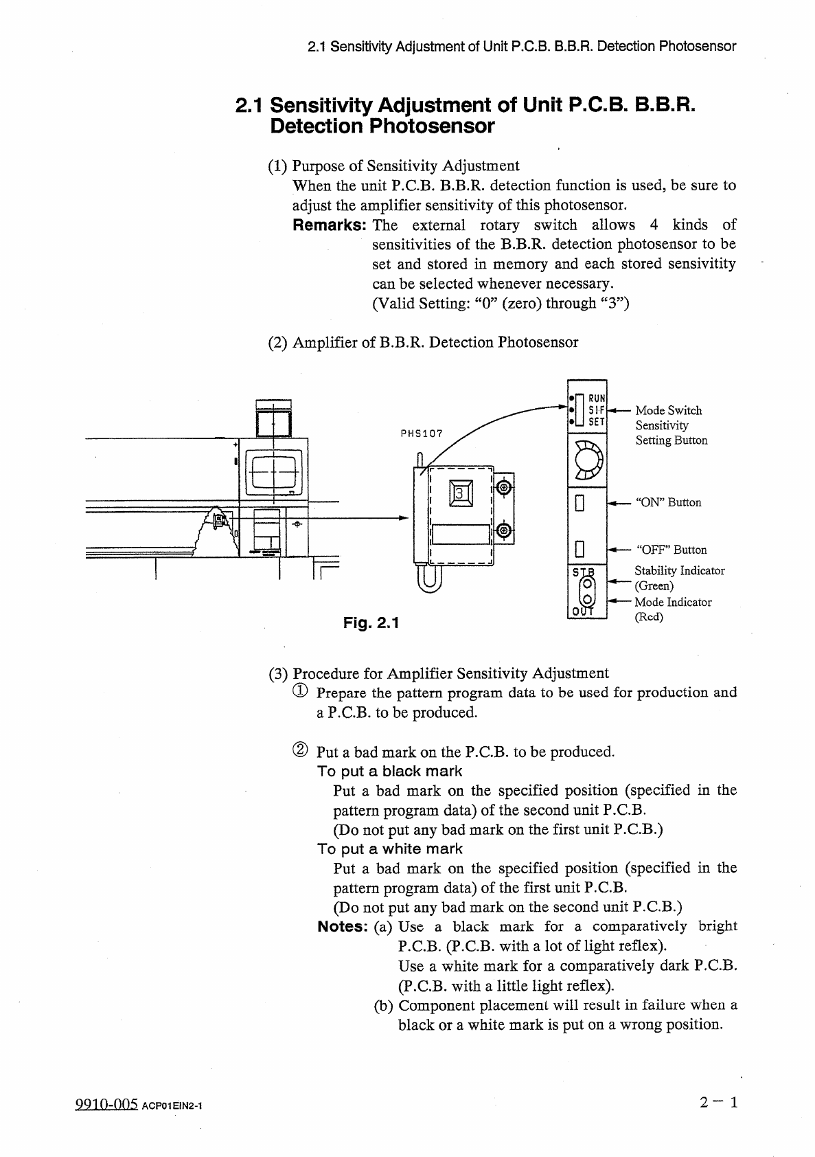
(
2
)
Amplifier
of
B
.
B
.
R
.
Detection
Photosensor
•
n
酬
S
—
Mode
Switch
Sensitivity
Setting
Button
D
□
.
“
ON
”
Button
31
□
一
“
OFF
”
Button
Stability
Indicator
(
Green
)
^
—
Mode
Indicator
(
Red
)
TF
S
01
Fig
.
2.1
(
3
)
Procedure
for
Amplifier
Sensitivity
Adjustment
①
Prepare
the
pattern
program
data
to
be
used
for
production
and
a
P
.
C
.
B
.
to
be
produced
.
②
Put
a
bad
mark
on
the
P
.
C
.
B
.
to
be
produced
.
To
put
a
black
mark
Put
a
bad
mark
on
the
specified
position
(
specified
in
the
pattern
program
data
)
of
the
second
unit
P
.
C
.
B
.
(
Do
not
put
any
bad
mark
on
the
first
unit
P
.
C
.
B
.
)
To
put
a
white
mark
Put
a
bad
mark
on
the
specified
position
(
specified
in
the
pattern
program
data
)
of
the
first
unit
P
.
C
.
B
.
(
Do
not
put
any
bad
mark
on
the
second
unit
P
.
C
.
B
.
)
Notes
:
(
a
)
Use
a
black
mark
for
a
comparatively
bright
P
.
C
.
B
.
(
P
.
C
.
B
.
with
a
lot
of
light
reflex
)
.
Use
a
white
mark
for
a
comparatively
dark
P
.
C
.
B
.
(
P
.
C
.
B
.
with
a
little
light
reflex
)
.
(
b
)
Component
placement
will
result
in
failure
when
a
black
or
a
white
mark
is
put
on
a
wrong
position
.
2
—
1
QQ
10
-
005
ACP
01
E
1
N
2
-
1
2.1
Sensitivity
Adjustment
of
Unit
P
.
C
.
B
.
B
.
B
.
R
.
Detection
Photosensor
③
Place
the
P
.
C
.
B
.
to
be
produced
on
the
X
/
Y
table
.
Then
,
use
the
X
/
Y
table
test
(
PLACEMENT
POSITION
/
STEP
OPERATION
)
to
move
the
bad
mark
on
the
first
unit
P
.
C
.
B
.
until
it
is
located
under
the
photosensor
.
Notes
:
(
a
)
The
step
No
.
at
the
“
X
/
Y
TABLE
TEST
”
display
does
not
represent
the
location
of
the
bad
mark
.
(
b
)
When
the
X
/
Y
table
test
(
P
.
E
.
C
.
CAMERA
POSITION
/
STEP
OPERATION
)
is
used
,
the
sensitivity
cannot
be
adjusted
because
the
bad
mark
does
not
move
to
the
area
under
the
photosensor
.
④
Set
the
[
OPERATION
/
SET
UP
]
switch
to
the
“
SET
UP
”
side
and
open
the
safety
door
.
Press
the
[
CLEAR
ALARM
]
key
to
turn
off
only
the
alarm
sound
and
continue
your
work
.
⑤
Specify
the
number
(
memory
No
.
)
of
the
amplifier
’
s
rotary
switch
and
open
the
plastic
cover
of
the
amplifier
.
Note
:
Hold
the
lower
side
of
the
plastic
cover
and
pull
it
forward
to
open
,
⑥
Set
the
mode
switch
of
the
amplifier
to
the
“
SET
”
side
.
⑦
Press
the
“
ON
”
button
.
Be
sure
to
release
your
finger
from
the
button
wihtin
3
seconds
.
When
the
“
ON
”
mode
is
accepted
,
the
stability
indicator
(
green
)
blinks
and
the
mode
indicator
(
red
)
illuminates
.
⑧
Close
the
safety
door
,
set
the
[
OPERATION
/
SET
UP
]
switch
to
the
“
OPERATION
”
side
,
and
press
the
[
RESET
]
button
.
After
that
,
continue
to
perform
the
X
/
Y
table
test
until
the
bad
mark
of
the
second
unit
P
.
C
.
B
.
is
located
under
the
photosensor
.
⑨
Set
the
[
OPERATION
/
SET
UP
]
switch
to
the
“
SET
UP
,
,
side
and
open
the
safety
door
.
Then
,
press
the
[
CLEAR
ALARM
]
key
to
turn
off
the
alarm
and
continue
your
work
.
⑩
Press
the
“
OFF
”
button
.
Be
sure
to
release
your
finger
from
the
button
wihtin
3
seconds
.
When
there
is
enough
difference
in
the
intensity
of
received
light
between
“
ON
”
and
“
OFF
”
modes
and
a
bad
mark
can
be
detected
in
a
stable
condition
,
the
stability
indicator
blinks
twice
.
Otherwise
,
the
indicator
blinks
continuously
15
times
.
In
this
case
,
re
-
perform
the
adjustment
②
and
follow
the
subsequent
steps
.
⑪
After
the
sensitivity
adjustment
,
set
the
mode
switch
of
the
amplifier
to
the
“
RUN
”
side
and
close
the
plastic
cover
of
the
amplifier
.
2
-
2
991
0
-
005
ACP
01
E
1
N
2
-
2