3MAINTENANCE__O.pdf - 第93页
3.3 Manual Nozzle Bypass 3.3 Manual Nozzle Bypass When the [ MANUAL NOZZLE BYPASS ] key is pressed at the “ SPECIAL SEL • ” display , the following display appears on the screen . Fig . 3.2 ( 1 ) Head Section ( Color of …
3.2
“
SPECIAL
SEL
.
"
Display
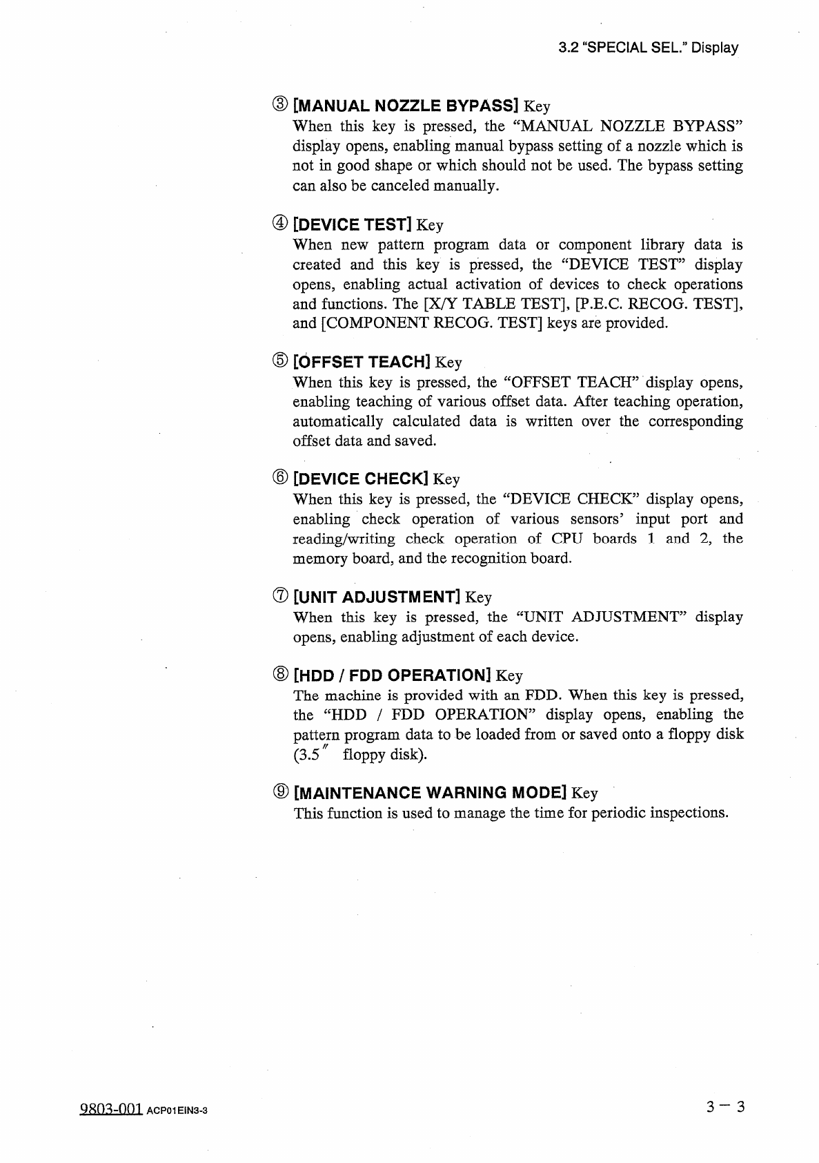
③
[
MANUAL
NOZZLE
BYPASS
]
Key
When
this
key
is
pressed
,
the
“
MANUAL
NOZZLE
BYPASS
”
display
opens
,
enabling
manual
bypass
setting
of
a
nozzle
which
is
not
in
good
shape
or
which
should
not
be
used
.
The
bypass
setting
can
also
be
canceled
manually
.
④
[
DEVICE
TEST
]
Key
When
new
pattern
program
data
or
component
library
data
is
created
and
this
key
is
pressed
,
the
“
DEVICE
TEST
”
display
opens
,
enabling
actual
activation
of
devices
to
check
operations
and
functions
.
The
[
X
/
Y
TABLE
TEST
]
,
[
P
.
E
.
C
.
RECOG
.
TEST
]
,
and
[
COMPONENT
RECOG
.
TEST
]
keys
are
provided
.
⑤
[
OFFSET
TEACH
]
Key
When
this
key
is
pressed
,
the
“
OFFSET
TEACH
”
display
opens
,
enabling
teaching
of
various
offset
data
.
After
teaching
operation
,
automatically
calculated
data
is
written
over
the
corresponding
offset
data
and
saved
.
⑥
[
DEVICE
CHECK
]
Key
When
this
key
is
pressed
,
the
“
DEVICE
CHECK
”
display
opens
,
enabling
check
operation
of
reading
/
writing
check
operation
of
CPU
boards
1
and
2
,
the
memory
board
,
and
the
recognition
board
.
sensors
5
input
port
and
various
⑦
[
UNIT
ADJUSTMENT
]
Key
When
this
key
is
pressed
,
the
“
UNIT
ADJUSTMENT
”
display
opens
,
enabling
adjustment
of
each
device
.
⑧
[
HDD
/
FDD
OPERATION
]
Key
The
machine
is
provided
with
an
FDD
.
When
this
key
is
pressed
,
the
“
HDD
/
FDD
OPERATION
”
display
opens
,
enabling
the
pattern
program
data
to
be
loaded
from
or
saved
onto
a
floppy
disk
(
3.5
〃
floppy
disk
)
.
⑨
[
MAINTENANCE
WARNING
MODE
]
Key
This
function
is
used
to
manage
the
time
for
periodic
inspections
.
3
-
3
QRO
^
-
nm
ACP
01
EIN
3
-
3
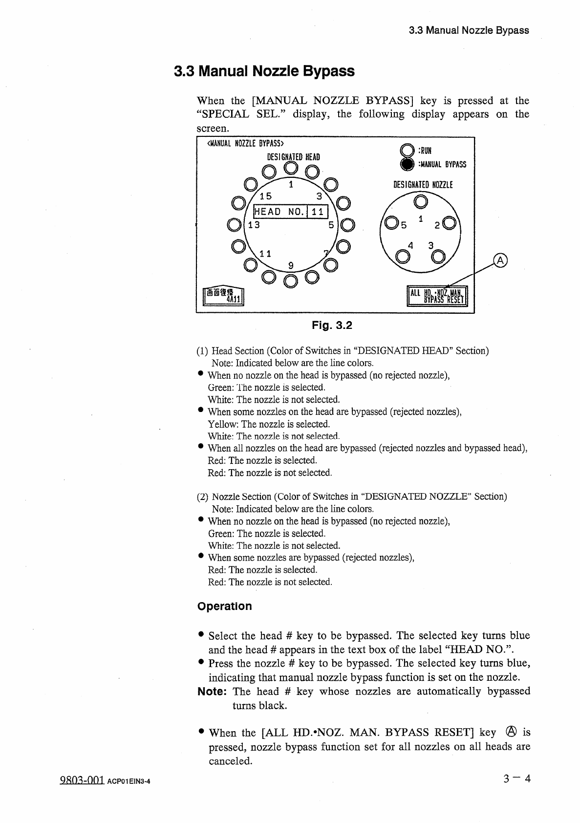
3.3
Manual
Nozzle
Bypass
3.3
Manual
Nozzle
Bypass
When
the
[
MANUAL
NOZZLE
BYPASS
]
key
is
pressed
at
the
“
SPECIAL
SEL
•
”
display
,
the
following
display
appears
on
the
screen
.
Fig
.
3.2
(
1
)
Head
Section
(
Color
of
Switches
in
“
DESIGNATED
HEAD
”
Section
)
Note
:
Indicated
below
are
the
line
colors
.
•
When
no
nozzle
on
the
head
is
bypassed
(
no
rejected
nozzle
)
,
Green
:
The
nozzle
is
selected
.
White
:
The
nozzle
is
not
selected
.
•
When
some
nozzles
on
the
head
are
bypassed
(
rejected
nozzles
)
,
Yellow
:
The
nozzle
is
selected
.
White
:
The
nozzle
is
not
selected
.
•
When
all
nozzles
on
the
head
are
bypassed
(
rejected
nozzles
and
bypassed
head
)
,
Red
:
The
nozzle
is
selected
.
Red
:
The
nozzle
is
not
selected
.
(
2
)
Nozzle
Section
(
Color
of
Switches
in
“
DESIGNATED
NOZZLE
”
Section
)
Note
:
Indicated
below
are
the
line
colors
.
•
When
no
nozzle
on
the
head
is
bypassed
(
no
rejected
nozzle
)
,
Green
:
The
nozzle
is
selected
.
White
:
The
nozzle
is
not
selected
.
•
When
some
nozzles
are
bypassed
(
rejected
nozzles
)
,
Red
:
The
nozzle
is
selected
.
Red
:
The
nozzle
is
not
selected
.
Operation
•
Select
the
head
#
key
to
be
bypassed
.
The
selected
key
turns
blue
and
the
head
#
appears
in
the
text
box
of
the
label
“
HEAD
NO
.
”
.
•
Press
the
nozzle
#
key
to
be
bypassed
.
The
selected
key
turns
blue
,
indicating
that
manual
nozzle
bypass
function
is
set
on
the
nozzle
.
Note
:
The
head
#
key
whose
nozzles
are
automatically
bypassed
turns
black
.
•
When
the
[
ALL
HD
.
^
NOZ
.
MAN
.
BYPASS
RESET
]
key
@
is
pressed
,
nozzle
bypass
function
set
for
all
nozzles
on
all
heads
are
canceled
.
3
-
4
g
^
-
nm
ACP
01
EIN
3
-
4
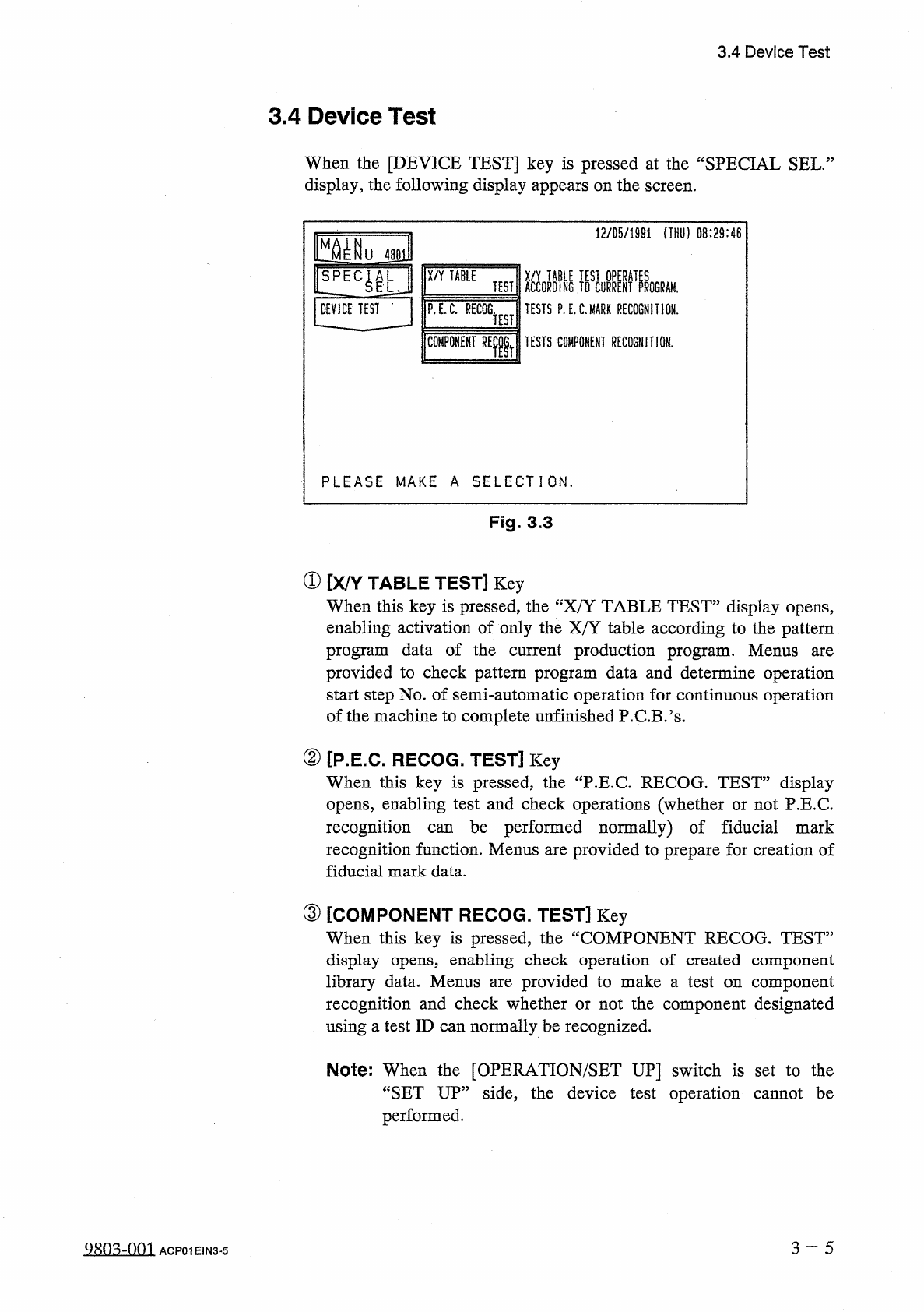
3.4
Device
Test
3.4
Device
Test
When
the
[
DEVICE
TEST
]
key
is
pressed
at
the
“
SPECIAL
SEL
.
display
,
the
following
display
appears
on
the
screen
.
12
/
05
/
1991
(
THU
)
08
:
29
:
46
^
MENU
48
E
X
/
Y
TABLE
ACCORDING
TESTS
P
.
E
.
C
.
MARK
RECOGNITION
.
TEST
!
ROGRAM
.
DEVICE
TEST
-
P
.
E
.
C
.
RECOG
.
TEST
COMPONENT
RElr
TESTS
COMPONENT
RECOGNITION
.
PLEASE
MAKE
A
SELECTION
.
Fig
.
3.3
①
[
X
/
Y
TABLE
TEST
]
Key
When
this
key
is
pressed
,
the
“
X
/
Y
TABLE
TEST
”
display
opens
,
enabling
activation
of
only
the
X
/
Y
table
according
to
the
pattern
program
data
of
the
current
production
program
.
Menus
provided
to
check
pattern
program
data
and
determine
operation
start
step
No
.
of
semi
-
automatic
operation
for
continuous
operation
of
the
machine
to
complete
unfinished
P
.
C
.
B
.
’
s
.
are
②
[
P
.
E
.
C
.
RECOG
.
TEST
]
Key
When
this
key
is
pressed
,
the
“
P
.
E
.
C
RECOG
.
TEST
”
display
opens
,
enabling
test
and
check
operations
(
whether
or
not
P
.
E
.
C
.
recognition
recognition
function
.
Menus
are
provided
to
prepare
for
creation
of
fiducial
mark
data
.
be
performed
normally
)
of
fiducial
mark
can
③
[
COMPONENT
RECOG
.
TEST
]
Key
When
this
key
is
pressed
,
the
“
COMPONENT
RECOG
.
TEST
”
display
opens
,
enabling
check
operation
of
created
component
library
data
.
Menus
recognition
and
check
whether
or
not
the
component
designated
using
a
test
ID
can
normally
be
recognized
.
provided
to
make
a
test
on
component
are
Note
:
When
the
[
OPERATION
/
SET
UP
]
switch
is
set
to
the
“
SET
UP
”
side
,
the
device
test
operation
cannot
be
performed
.
3
~
5
Q
8
n
.
^
-
nni
ACP
01
EIN
3
-
5