KE2020-Instruction-Manual-ver1.30.pdf - 第168页
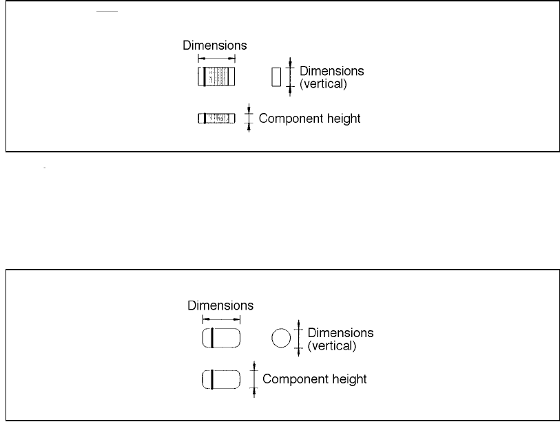
4 – 66 4.7.2.1 Exampl es of component dimensi ons See the f ollowing figur es to create dat a. The dimensions and shape of each type of component are shown below . • Square chip • MEL F (horizontal) (horizontal)
4 – 65
④ Outer dimensions (Width, Length)
Enter the component width and length, using the formula bar.
Input range: 0.01 mm to 150.00 mm
⑤ Outer dimensions (Height)
Enter the component height using the formula bar.
Input range: 0 to 25.00 mm
⑥ Other
Pick depth
Enter the distance from the side picked up with a nozzle to the top of the
projection of a component with using the formula bar.
Input range: 0 to 25.00 mm
The default value is “0”. Entry to this item may be required for a
component whose surface is not flat such as a connector.
Normally the default value can be applied to this item.
4 – 66
4.7.2.1 Examples of component dimensions
See the following figures to create data.
The dimensions and shape of each type of component are shown below.
• Square chip
• MELF
(horizontal)
(horizontal)
4 – 67
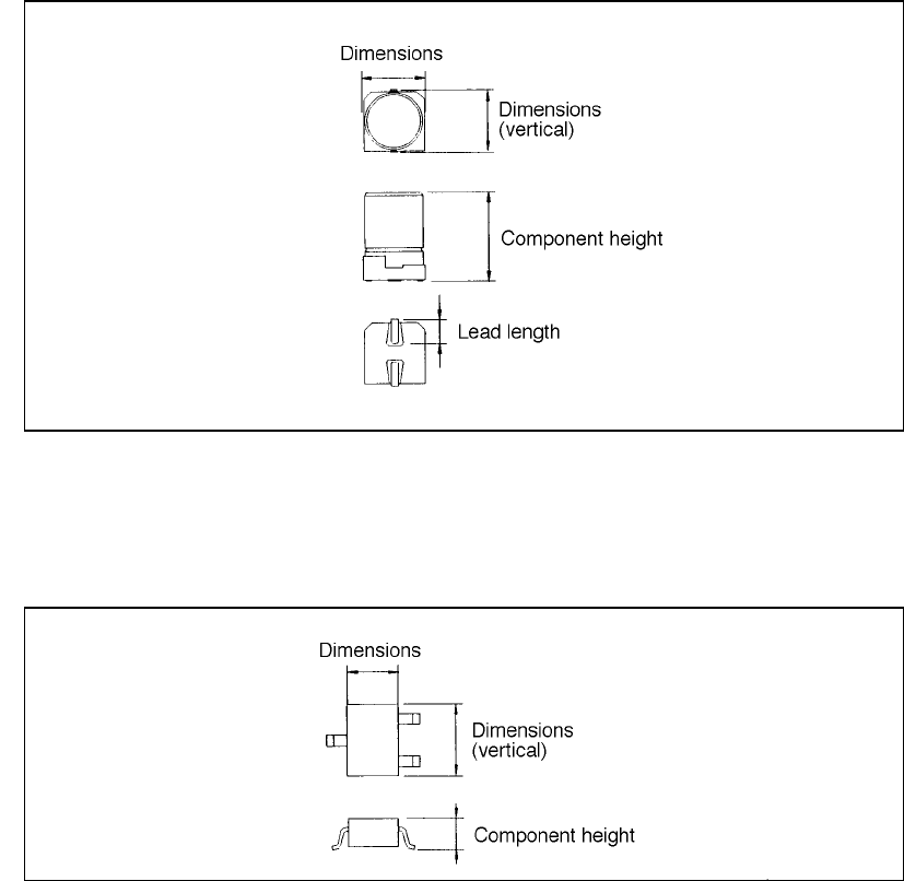
• Aluminum electrolytic capacitor
• SOT
(horizontal)
(horizontal)