KE2020-Instruction-Manual-ver1.30.pdf - 第194页
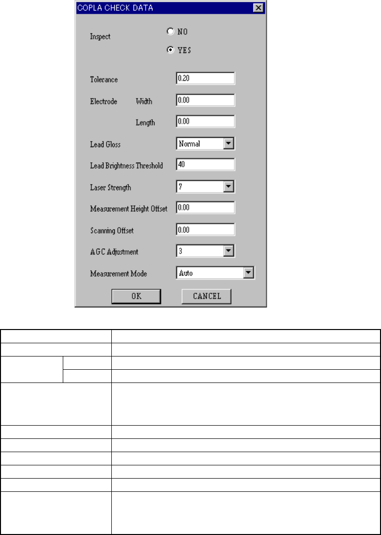
4 – 92 W hen y ou click the <Set> butt on, the f ollowing “COPLA CHECK DA T A” dialog box appears on the screen. Check Select whether to perform the coplanarity check or not. CoplaT oleran Set the value used for ju…
4 – 91
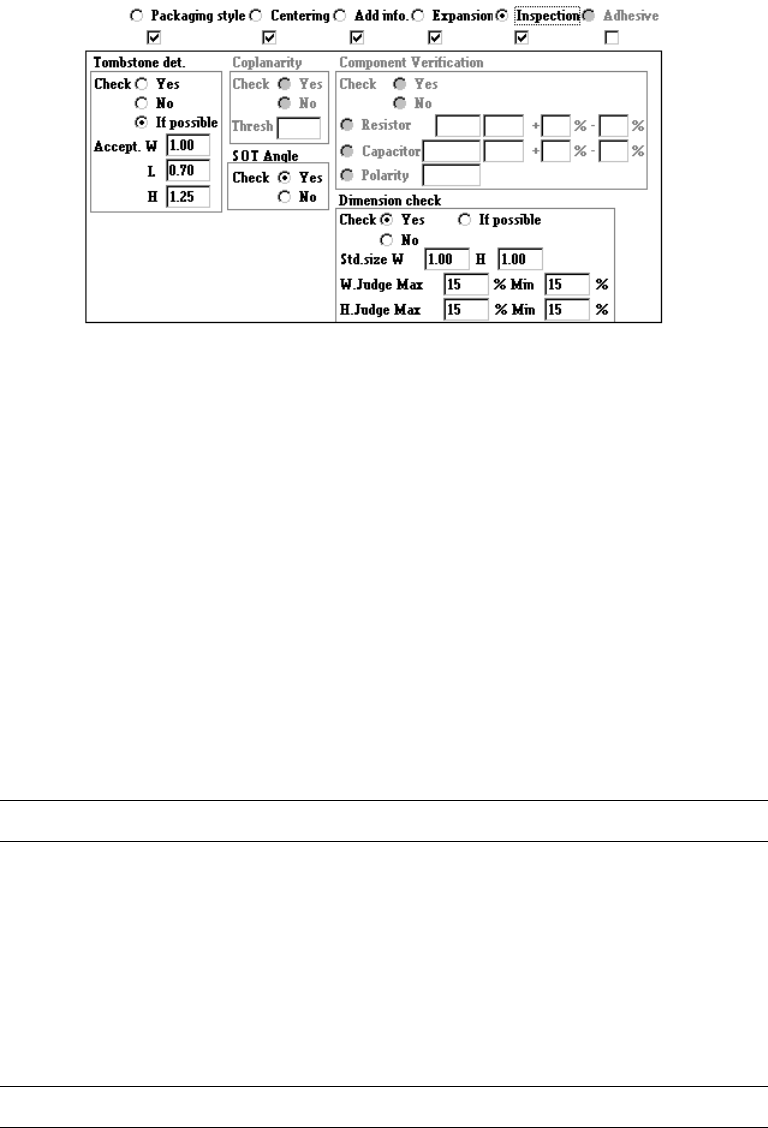
4.7.7 Tack control section (Inspection page)
① Tombstone det.
Using the radio button, select whether to use the chip rise detecting option.
When you select “Yes” or “If possible”, enter values at the items “Accept. W”, “L”
and “H” also as the reference value. If you select “If possible”, the machine
detects a chip rise error when the chip rise detecting unit is installed on the
machine.
② Coplanarity
(1) Coplanarity (700)
Select whether floating of leads of IC components is checked with its radio
button.
When "Yes" is selected, the "Thresh" value is required.
L
This setting is available with a KE-700 series station only.
(2) Coplanarity (2000)
Specify whether to check if a lead of a component floats or not with using the
radio button.
When you check the radio button “YES”, the <Set> button is enabled.
Enter the coplanarity check data.
L
This setting is available with a KE-700 series station only.
4 – 92
When you click the <Set> button, the following “COPLA CHECK DATA” dialog
box appears on the screen.
Check Select whether to perform the coplanarity check or not.
CoplaToleran Set the value used for judgment.
Width Set the width of the electrode. Term Size
Length Set the length of the electrode.
TermCoat Set the lead coating information.
• tujou (Normal)
• Kotaku-Ari (Glossy)
• Kotaku-Nashi (Not glossy)
DarkThreshLvl Set the threshold value for the brightness of a lead.
Power Set the laser strength from 0 to 7.
MeasHeightOffset Set the offset for the measured height.
CoplaOffset Set the offset for the scanned position.
AGCLvl Set the AGC corrected value from 0 to 5.
ScnMode Set the measurement mode:
• Auto
• HyoujunSokutei-Mode (Normal measurement mode)
• Koseido Sokutei-Mode (High-precision measurement mode)
Click the <OK> button to validate your settings, or <CANCEL> button to cancel
your settings.
4 – 93
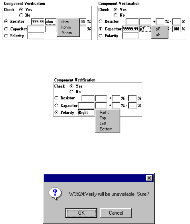
③ Verify
Using the radio button, select whether to verify a component: resistor, capacitor
and polarity.
When you select “Capacitor” or “Resistor”, enter the upper and lower limits of the
reference value, unit, tolerable error items.
To specify the unit, click the input area with the right button of a mouse. The
following pop-up menu appears on the screen.
When you check the radio button “Polarity”, you can select the direction by
clicking its input area with the mouse right button.
If the Verify check cannot be performed because another data was changed even
though the item “Check” is set to “Yes”, the following dialog box appears on the
screen.
④ Dimension check
Using the radio button, select whether to check the dimensions of a component.
When you select “If possible”, the machine checks the dimensions of a
component.
When you select “Yes”, the machine checks the dimensions of a component.