KE2020-Instruction-Manual-ver1.30.pdf - 第394页
5 − 52 L L L L W W W W L L L L W W W W L L L L W W W W Setting item Descripti on Cut shape S elect a c ut s hape of a lead: - Flat - U-shape cut - Cut at t he lower left c orner - Cut at t he lower right corner Cut lengt…
5 − 51
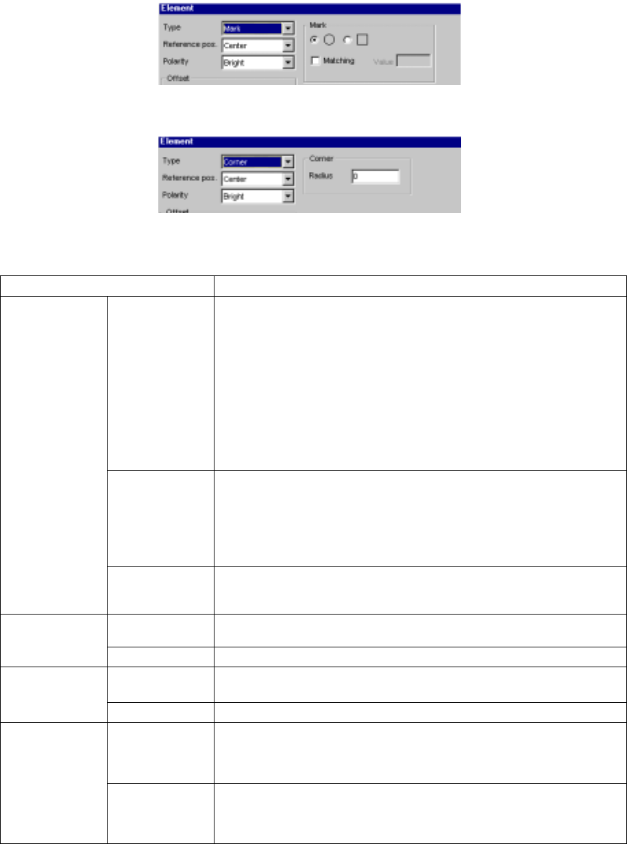
(5) When you select “Mark”
(6) When you select “Corner”
• Detailed description of each setting item
Setting item Description
Type Select an element type according to the “Dimension” setting as shown below:
1D
- Outer Lead (referred from the top view)
- Inner Lead (referred from the top view)
1D and 2D
- Ball (referred from the bottom view)
- Land (referred from the bottom view)
- Column (referred from the bottom view)
Point
- Mark (referred from the bottom view)
- Marginal area (referred from the top view)
- Side (referred from the top view)
- Corner (referred from the top view)
Reference pos.
(position)
(A displayed
value is set, and
fixed according to
the “Type”
setting.)
Select the element reference position:
- Center: center of an element (selected when “Ball”, “Land”, “Mark” or
“Marginal area” is selected)
- Center of the bottom side: (selected when “Outer Lead”, “Inner Lead” or
“Side” is selected) (for a lead component)
- Lower left position: (selected when “Corner” is selected)
Element
Polarity Select the brightness of an element:
- Bright
- Dark
X, Y, Z and Theta Set an offset if the coordinates set in the “Element Group” screen should be
offset further. (Not used)
Offset
Tolerance Set the allowable offset range. (Not used)
Size Enter the size of an element: dimensions of a lead.
- “X” indicates the width and “Y” indicates the length.
Element size
Tolerance Set the allowable size range. (Not used)
Profile Set the lead type:
- Flat
- Gullwing
- J-bent
Outer Lead/Inner
Lead
Coating Select coating applied to a lead:
- Bare (No plating)
- Gold-plating
- Solder-plating
5 − 52
L
LL
L
W
WW
W
L
LL
L
W
WW
W
L
LL
L
W
WW
W
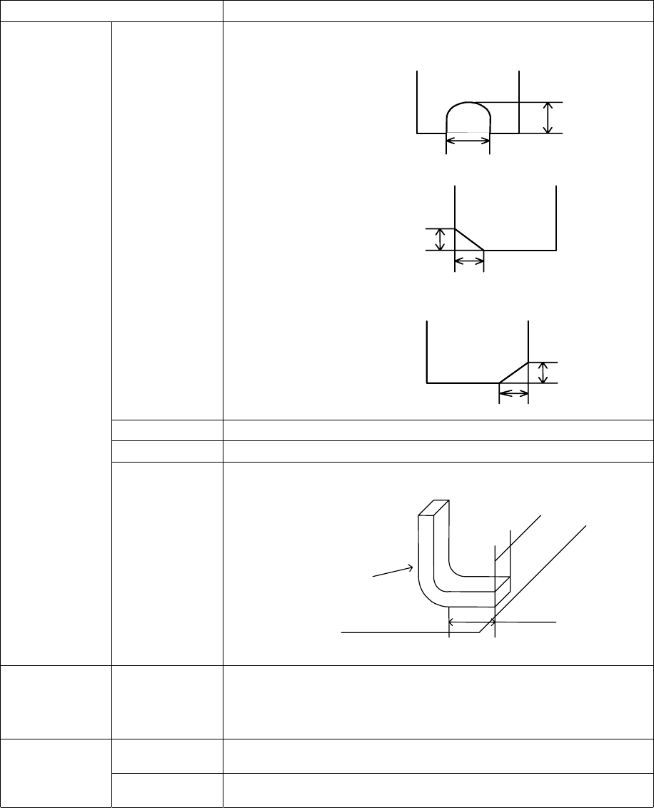
Setting item Description
Cut shape Select a cut shape of a lead:
- Flat
- U-shape cut
- Cut at the lower left corner
- Cut at the lower right corner
Cut length Enter the length of a cut portion of a lead (L).
Cut width Enter the width of a cut portion of a lead (W).
Lead size Enter the length and width of a foot portion of a lead.
Ball/Land/Column Inspection
(Diameter, Area,
Ball exist? And
Average
diameter)
Set whether to check a ball/land/column and the reference level.
OK Registers data and displays the “Element Group” or “Extended Array” screen
again.
Cancel Cancels data registering and displays the “Element Group” or “Extended Array”
screen again.
Length
Width
Lead
Board
5 − 53
5.2.4.4 Procedure for creating general-purpose vision component data
5.2.4.4.1 Lead components (Element group/Element format)
This section describes the procedure for creating data on lead components
(multi-lead components).
1) Operation on the “Extended Vision” screen
- Select “Lead Component” on the “Component Type” combo box.
- Check the “Element group/Element format” check box in the “Define data
format” field.
- Click the <Add> button on the “Element Group List”.
2) Operation on the “Element Group” screen
Define an element group on this screen.
An element group is composed of components whose lead size and pitch are the
same.
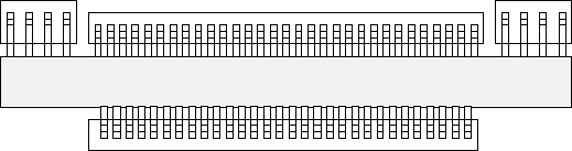
See Figure 5.2.4.4.1 for an example of a multi-lead component. The procedure
for creating data on this component is to be described below.
▼
▼▼
▼ Description
In the example below, four element groups are defined. The size and pitch of
leads of the first and third element groups are the same, while the direction and
position of leads of these groups are different from each another. The size and
pitch of leads of the second and fourth element groups are the same also, but
leads of these groups are not arrange continuously, so the lead pitch is not the
same. If the distance between these leads is an integral multiple of the specified
pitch, they can be defined as one element group that has an area having no lead.
However, we recommend that you define them as separate element groups.
To define the direction and position of the element group, specify the component
posture. In Figure 5.2.4.1.1, the direction of a component shown is normal. The
posture of multi-lead components is regulated from the top view.
Figure 5.2.4.4.1
Fourth element
group
Third element
group
Second
element group
First element
group
Top View