KE2020-Instruction-Manual-ver1.30.pdf - 第19页
1 − 10 Description of abbreviations ATC : Automatic Tool Chang er OCC : Offset Co rrection Camera EPU : External Progra mming Unit HLC : Host Line Computer HOD : Handheld Operating Device MTC : M atrix T ray Changer PW B…
1 − 9
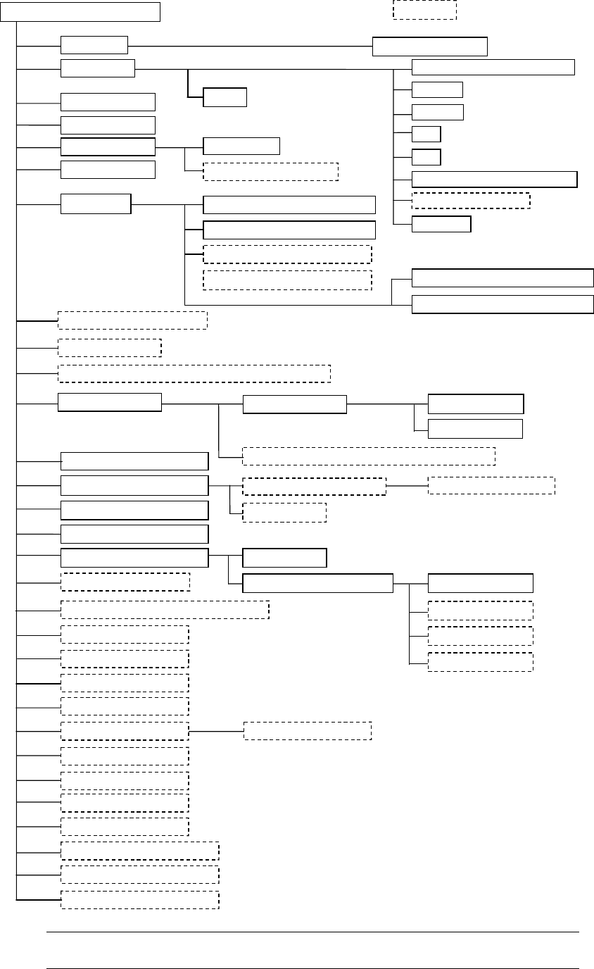
1.1.3 System configuration
Color liquid-crystal display (LCD)
Keyboard
Track ball
FDD
HDD
100 Base/10 Base Ethernet board T
Rear side operation unit
Area sensor
Signal tower
Emergency stop button
Placing head
Automatic tool changer (ATC)
Feeder float detecting function
Pneumatic piping system
Vision Centering System (VCS)
Batch feeder change function
Feeder bank driver
Verification function
Vision monitor
Feeder table
PWB conveyor unit
Placement station L
Automatic PWB transportation width adjustment device
Feeder position indicator function
Automatic tape cutter
Tape feeder
Stick feeder
Stack stick feeder
Non-stop operation function
Power unit
CPU board
I/O control CPU
Motor control unit
Cabinet
X-Y positioning unit
Function designed for a component whose height is 20 mm
Component recognition camera
IC collection belt
Tray holder
DTS
MTC
MTS
Bulk feeder
KE-2020M /KE-2020L/KE-2020E
Optional
Host Line Computer (HLC)
External Programming Unit (EPU)
Spare feeder change truck
Standard camera
Optional camera 1
Optional camera 2
Optional camera 3
Pin reference
Outline reference
Laser recognition head (MNLA)
Bad mark reader
Height Measurement System (HMS)
Offset correction camera (L)
Signal tower with the buzzer
UPS
Offset correction camera (R)
Laser/Vision recognition heads (FMLA)
*1
*1
*1
*1
*1
*1
*1
*1
*1
*1
*1
Coplanarity Function
SOT Direction Check Function *1
*1
Note:
Options marked with an asterisk "*" are to be installed onto the main
unit at the factory.
1 − 10
Description of abbreviations
ATC : Automatic Tool Changer
OCC : Offset Correction Camera
EPU : External Programming Unit
HLC : Host Line Computer
HOD : Handheld Operating Device
MTC : Matrix Tray Changer
PWB : Printed Wiring Board
VCS : Visual Centering System
HMS : Height Measurement System
CVS : Component Verification System
FPI : Feeder Position Indicator
MNLA : Multi Nozzle laser Align
DTS : Double Tray Server
MTS : Matrix Tray Server
MTC : Matrix Tray Changer
BMR : Bad Mark Reader
FMLA : Focused Moduler Laser Align

1 − 11
1.1.4 Mechanical specifications
(1) Placement accuracy
The following table lists the placement accuracy data for different types of
components. A poorer accuracy results depending on the components that may
have an edge or plastic mold burrs at the area detected with the laser align function,
and that may have a moving part to be detected with respect to the pick port.
Table 1.1.4.1
Unit: mm
Component type KE-2020
MNLA heads
(Laser recognition correction)
Component size 20 or less
FMLA heads
(VCS recognition correction)
Component size 50 or less
Square chip ± 0.08 −
MELF ± 0.1 −
SOT ± 0.15 −
Aluminum
electrolytic capacitor
± 0.3 ± 0.15
SOP ± 0.15 in the right angle direction against
the lead (Burr on one side: 0.15 or less)
±0.2 in the direction parallel to the lead
BOC mark: ± 0.08 in the right angle
direction against the lead
±0.12 in the direction parallel to the lead
PLCC, SOJ ± 0.2 Component positioning mark: ± 0.08
BOC mark: ± 0.1
QFP, TSOP
(Pitch: 0.8 or more)
± 0.12 Component positioning mark: ± 0.04
BOC mark: ± 0.06
QFP, TSOP
(Pitch: 0.65 or
more)
± 0.09 Component positioning mark: ± 0.04
BOC mark: ± 0.06
QFP, TSOP
(Pitch: 0.5 or more)
− ± 0.04,
Only a component positioning mark is
available.
Unidirectional lead
(Pitch: 0.5 or more)
− ± 0.04 in the right angle direction against
the lead
± 0.12 in the direction parallel to the lead
Only a component positioning mark is
available.
Components whose
image is divided,
then recognized.
− Component positioning mark:
± 0.06 in the right angle direction
against the lead
± 0.12 in the direction parallel to the
lead
BOC mark:
± 0.1 in the right angle direction against
the lead
± 0.12 in the direction parallel to the
lead
BGA ± 0.2 Component positioning mark: ± 0.08
BOC mark: ± 0.12
FBGA − ± 0.06,
Only a component positioning mark is
available.
Other large-size
components
± 0.3 −
(2) Placement cycle time
The optimized placement cycle time is shown below. The cycle time required
when a component is placed on a board actually varies depending on the board
size or how many times a nozzle is replaced.