KE2020-Instruction-Manual-ver1.30.pdf - 第309页
4 – 207 4.12.3.4. 2 Vision recognit ion inspecti on operation (1) Vision recognit ion operation W hen you select the [ Vision recognit ion] comm and, the f ollowing dialog box appears on the screen. Figure 4.12.3. 4.2 “V…
4 – 206
4.12.3.4 Check operation with vision recognition
4.12.3.4.1 Operation transition during checking a component with vision recognition
The displayed screen and the system state are changed during checking a
component with the vision recognition function as shown below.
Figure 4.12.3.4.1 State transition while the system is checking a component with
vision recognition
User operation
Process
Dialog box
Process
onl
y
Check of a
component with
vision reco
g
nition
Selection
“Vision inspection” dialog
b
Return.
Check
“Executing inspection”
dialog box box
Correct/Error
Teaching
HOD device key
Feeder
ENTER/
CANCEL
PREV/NEXT
Feeder knock
Change of a component
p
ick-u
p
p
osition
4 – 207
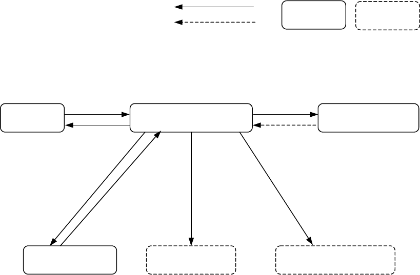
4.12.3.4.2 Vision recognition inspection operation
(1) Vision recognition operation
When you select the [Vision recognition] command, the following dialog box
appears on the screen.
Figure 4.12.3.4.2 “Vision inspection” dialog box
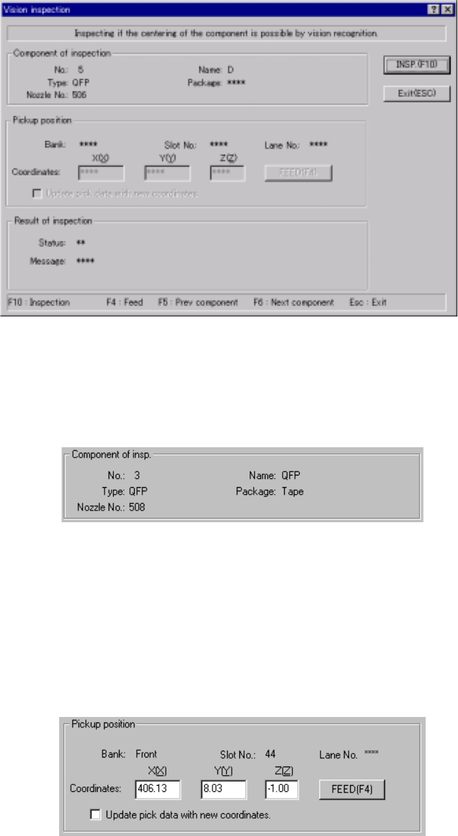
1) Component of insp. (inspection)
Component data required to perform the vision recognition inspection
appears on the dialog box.
Figure 4.12.3.4.3 “Component of insp.” Section
2) Pickup position
Data on the component pick-up position appears on the dialog box. You
can change the component pick-up position to the previous or next
alternate component position also. If there is no Pick data created, or if
“MTC” is specified as a feeder, each item on this section is not displayed,
so you cannot change the component pick-up position, perform the
feeder-knock operation or teaching operation.
Figure 4.12.3.4.4 Pick-up position of a component to be checked
4 – 208
① <FEED> button
This button knocks a feeder once to feed a component (except a 32-mm
paper tape).
② “Update pick data with new coordinates”
Check this check box to use the HOD device and store the taught result in
Pick data.
If you do not check this box, the taught coordinates are applied to the
current pick-up operation only.
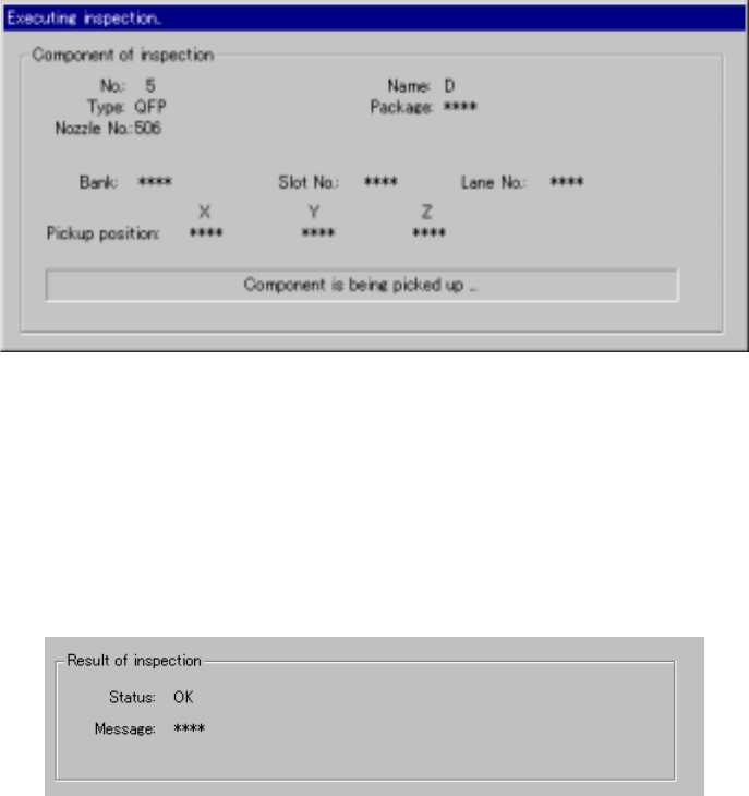
3) “Executing inspection” screen
While the system is checking a component with the vision recognition
function, the following dialog box appears on the screen. On this dialog
box, data on a component being inspected and its pick-up position are
displayed. The process being performed is also displayed.
Figure 4.12.3.4.5 “Executing inspection” screen
4) Result of inspection
After checking a component, the system displays the result in the “Result
of inspection” section of the screen. “OK” appears if a component can be
centered based on its vision, while “NG” and the reason of an error
appear in the “Message” space if not.
Figure 4.12.3.4.6 “Result of inspection” section
5) <INSP.> button
This button checks a component with the vision recognition function.
6) <Exit (ESC)> button
This button finishes checking a component with the vision recognition
function and returns to the previous screen.