KE2020-Instruction-Manual-ver1.30.pdf - 第414页
5 − 72 5.2.5 Ctrl (Control) W hen y ou click the [Edit] command displayed on the “Ct rl” f ield, the f ollowing screen appears. • Set t he light used for recogn izing divided image in the f ollowing order : 1. Set a VCS …
5 − 71
5. Outline-recognized components
- If you define an outline-recognized component with only one type of element
(corner, side or mark) other than a lead and ball, you have to specify two or
more corresponding elements. If you specify another type of element also,
you only have to specify one corresponding element (excluding a side).
- Up to four corners can be specified for this type of component. Note that you
cannot specify two or more corners whose specified angle is the same (theta
offset).
- If another corner or an element (lead, rectangular land or rectangular mark)
having a corner whose angle is the same is located near one corner element,
they should be far from one another by 4 mm or more provided that the
standard VCS is used.
(Since an intersection point outside the outer frame is regarded as a corner
due to the Version 1.10 limitations, two corners (or corner-shaped substance)
should be far from one another by 4 mm or more also.)
- Up to four sides can be specified per component. However, note that two or
more sides whose specified angle is the same (theta offset) cannot be
specified per component. A side should be located on the outer frame, and
its length should be half or longer of the dimension of the component. When
you specify a side (sides) only as an element, include two sides that are
orthogonal
to one
another.
- Up to three marks can be specified per component.
- You can specify a hole as a circle mark of the reverse polarity (dark). In this
case, it has to be displayed as a circle clearly on the screen. (Note that a
hole may not be displayed as a circle clearly on the screen when a thick
component is to be recognized with the perspective light.)
- A mark should be located far from a similar-sized mark or similar-shaped and
similar-sized element (ball or circular land) by 5 mm or more provided that the
standard VCS is used.
6. Notes when a general-purpose vision component data format is used
- Use this format for an element group (especially lead element group) whose
positioning precision is sufficient to be recognized. When you use this format
for an element group (especially lead element group) whose positioning
precision is uncertain, a recognition error may occur frequently.
ー
θ270°Corner
θ0°
Corner2
θ0°
Corner1
θ90°Corner
θ180°Corner
Although there are two corners
whose theta angle is 0 degrees, you
can specify just one corner of them.
<TOP VIEW>
ー
θ270°
Side 1
θ0°
Side 2
θ0°Corner1
θ90°Side
θ180°Side
θ270°
Side 2
Although there are two sides whose
theta angle is 0 degrees and those
whose theta angle is 270 degrees
respectively, you can specify only
either of two sides whose angle is
the same.
<TOP VIEW>
5 − 72
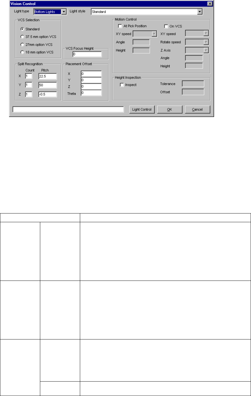
5.2.5 Ctrl (Control)
When you click the [Edit] command displayed on the “Ctrl” field, the following screen
appears.
• Set the light used for recognizing divided image in the following order:
1. Set a VCS used for recognizing a component.
2. Determine the division recognition.
3. Specify the Light type and sub type (when the Light type is “Back lights” or
“Side lights”).
4. Set the other items.
• Detailed description of each setting item
Item Description
Light type Select the light type:
- Bottom Lights
This type of light is a red light consisting of three light blocks: coaxial light
(half mirror light), bottom light and red side light (upper and lower stages).
- Back Lights
This type of light is a green light used for using the shade of a component
to center the component that cannot be illuminated with the back light.
- Side Lights
This is a light (normally blue light) used for recognizing a solder ball of a
BGA (FBGA).
Sub type Select the sub light type.
Bottom
- Standard
- CBGA
- LGA
Side
- Red side light
- Red side light equipped with a pop-up light
- Blue side light
- Blue side light equipped with a pop-up light
Count Set the number of divisions of image in the X, Y and Z directions.
The number of divisions in each direction is:
X: 1 to 2
Y: 1 to 3
Z: 1 to 2
(See Section 5.2.5.1 “Applicable component dimensions during division
recognition”.)
Split
recognition
Pitch Specify the distance over which a VCS moves. The value range varies
depending on the selected VCS.
5 − 73
Item Description
VCS
Selection
Select a VCS used for recognizing a component:
Standard (50 mm)
37.5 mm option VCS
27 mm option VCS
18 mm option VCS
VCS Focus
Height
Specify the height the VCS recognizes.
(Distance from the component bottom to the lead bottom side)
Placement
Offset
X, Y, Z, θ
Enter an offset for each component which is used for placement. Note that
this offset functions in the same manner the recognition offset of
Component data does.
At Pick
Position
Check this check box when you set the posture of a component at the
pick-up position.
(The machine checks the posture of a component when it picks up the
component, then moves it onto the VCS.)
XY speed Select the speed for controlling the posture of a component:
- Very Slow (default)
- Slow
- Medium
- High
Angle Enter the angle of the component posture after it is picked up.
Allowable input range: 0 to 359 degrees (default: 90 degrees)
This angle is automatically and optimally controlled.
Height Enter the height when a component is being rotated.
Allowable input range: - 20.0 mm to 20.0 mm (default: 0 mm)
On VCS Check this check box when you want to set the component posture control
on the VCS.
(This item is available only for a large component.) (When the machine
recognizes divided images of a component)
XY speed Select the speed for recognizing divided images of a component:
- Very Slow
- Slow
- Medium
- High
Rotate speed Select the rotation speed when the machine recognizes divided images of a
component:
- Very Slow
- Slow
- Medium
- High
Z Axis Select the speed of the Z axis when the machine recognizes divided
images of a component:
- Very Slow
- Slow
- Medium
- High
Angle Enter the posture of a component when the machine recognizes it.
Allowable input range: 90 degrees
The angle is automatically and optimally controlled.
Motion
Control
Height Enter the height of a component when it is being rotated (Not used).
Allowable input range: - 20.0 mm to 20.0 mm
OK Sets the data.
Cancel Cancels the data setting.