KE2020-Instruction-Manual-ver1.30.pdf - 第368页
5 − 26 ⑫ Base Style Set the base style of a BG A component. This item is available only w hen you select “All balls” or “All land” at t he “Contrast ” sett ing item . A base st yle is combined with a ball pattern, then u…
5 − 25
9
10
11
12
13
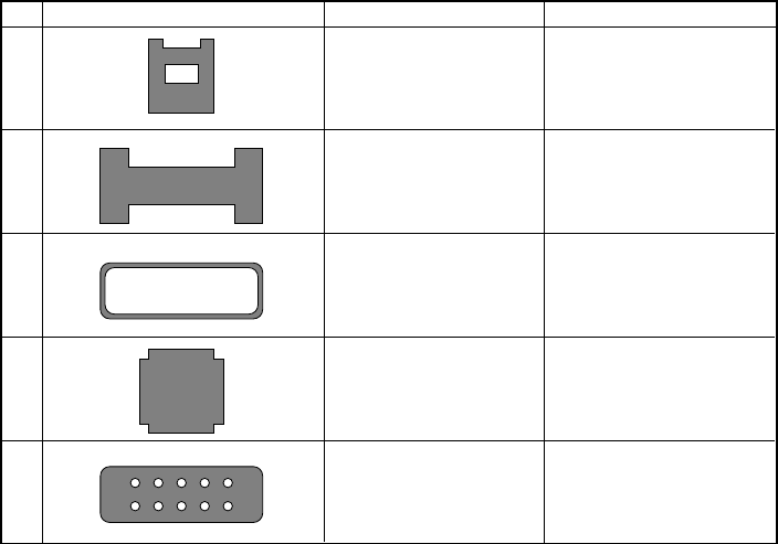
The side shape is concave.
The inside of the component
is undefined.
The side shape is concave.
However, only components
of point symmetry.
The inside of the component
is hollow. The outline edge
should be 0.3 mm or more.
Missing corner
Missing corner. The inside
shape is undefined.
Corner recognition
Corner recognition
Center recognition (Note)
Side recognition
Center recognition (Note)
Side recognition
Side recognition
Center recognition (Note)
No. Recognition component shape Recognition method Remarks
Note: Center recognition is enabled when the longer side is twice or more as long as the shorter side.
5 − 26
⑫ Base Style
Set the base style of a BGA component. This item is available only when you
select “All balls” or “All land” at the “Contrast” setting item.
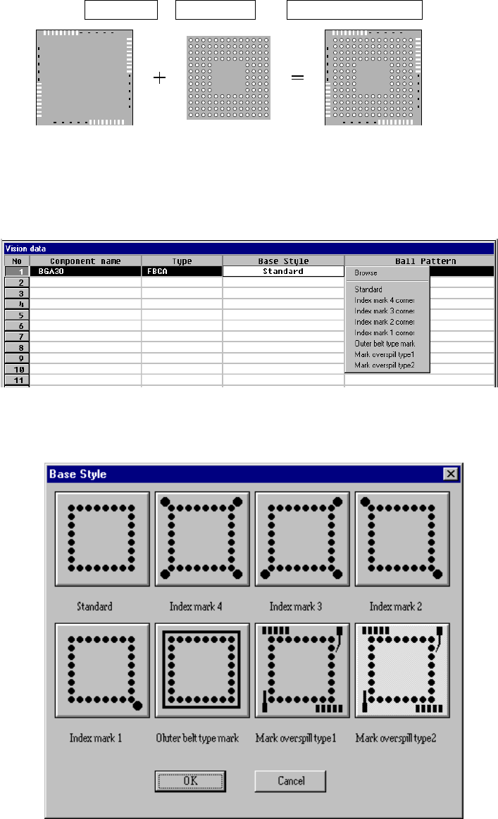
A base style is combined with a ball pattern, then used as a recognition
pattern.
Base style + Ball pattern → Recognition pattern
Ball pattern
Default pattern
User pattern
Base style Recognition pattern
• How to set
When you click this setting item with the right button, the selection
pop-up menu appears on the screen.
◇ When you select Browse
Figure 6.7-2-18 (b) “Base Style” browser dialog box
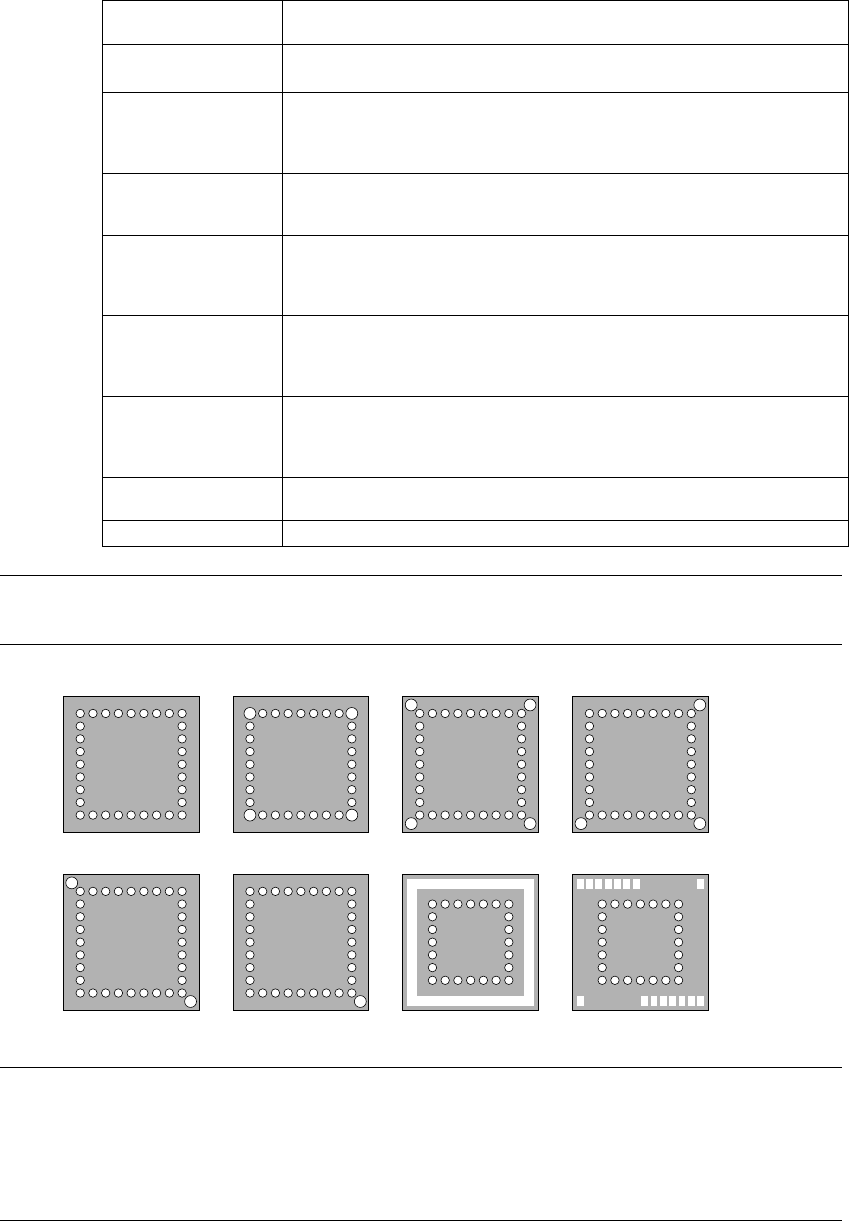
5 − 27
• Setting items
Selection on the
pop-up menu
Base style
Browse Displays sample images: from “Standard” to “Mark over spill”, and allows
you to select the desired style from the displayed images.
Standard There are only balls located on the outer frame of a package.
This setting is available for a conventional BGA whose pitch is narrow and
whose balls are small. This is available also for a component whose index
balls are on the grid.
Index mark 4 corner There are only balls and index balls on the outer frame of a package, and
index balls are outside the grid.
Index balls are located at four corners outside the grid.
Index mark 3 corner There are only balls and index balls on the outer frame of a package, and
index balls are outside the grid.
Index balls are located at three corners outside the grid (when there is no
index ball at the lower left corner, it should be called 0 degrees).
Index mark 2 corner There are only balls and index balls on the outer frame of a package, and
index balls are outside the grid.
Index balls are located at two corners outside the grid (when there is no
index ball at the lower left and right corners, it should be called 0 degrees).
Index mark 1 corner There are only balls and index balls on the outer frame of a package, and
index balls are outside the grid.
Index balls are located at one corner outside the grid (when there is no
index ball at the lower right corner, it should be called 0 degrees).
Outer belt type mark There is something whose density is similar with a ball like a belt on the
outer frame of a package.
Mark over spill There is something other than a ball on the outer frame of a package.
Note: An index mark is not a ball but a mark that indicates a certain position, or
ball-shaped substance used for partial pressure.
■ Default base style sample image
Standard Index mark 4 corner Index mark 3 corner
Outer belt type mark Mark overspillIndex mark 2 corner Index mark 1 corner
Note: The size of an index ball varies and the center of an index ball and that of a
ball are not always aligned with each another on a line. To clearly identify
each setting of “Index mark 4 corner”, “Index mark 3 corner”, “Index mark 2
corner” and “Index mark 1 corner”, we define the index ball position and its
corresponding setting as follows.