KE2020-Instruction-Manual-ver1.30.pdf - 第345页
5 − 3 ⑤ QFJ ( PLCC) (T op view) ⑥ One- way lead connector (T op view) ⑦ BGA, FBGA (Bottom v iew ) Normal assignment Stagger assignm ent Note: The ball diameter shall be ent ered as lead width, and ball pitch as lead pitc…
5 − 2
5.2 Vision Data Input
Vision data is used to recognize the component using vision recognition function.
The vision data can be entered only for the component types shown below and which
have been selected for vision centering of the component data.
QFP, SOP, TSOP, TSOP2, PLCC (QFJ), BAG, SOJ, PQFP (BQFP) one-way lead
connector, J lead socket, gull wing socket, socket with bumper, aluminum electrolytic
capacitor, and GaAsFET, two-way lead connector, SOP (with a heat sink), FBGA, Z
style lead connector
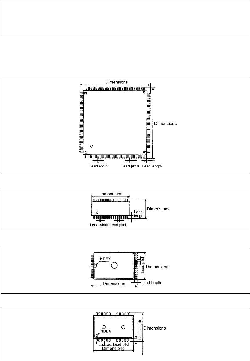
• The following shows the component types. For data setting, it is defined to 0° of the
components when the components are oriented as shown below.
① QFP (Top view)
② SOP (Top view)
③ TSOP (Top view)
④ TSOP2 (Top view)
5 − 3
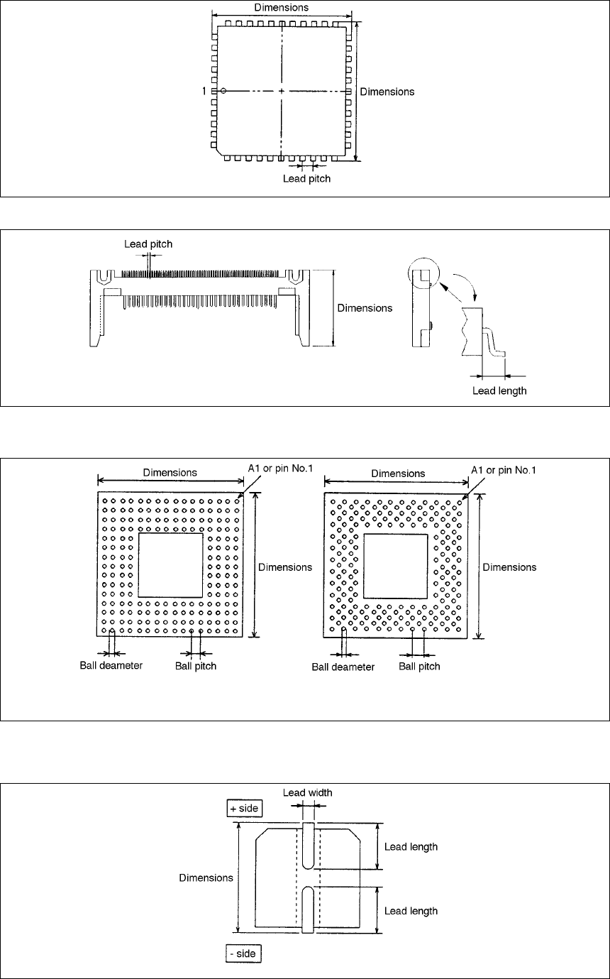
⑤ QFJ (PLCC) (Top view)
⑥ One-way lead connector (Top view)
⑦ BGA, FBGA (Bottom view)
Normal assignment Stagger assignment
Note: The ball diameter shall be entered as lead width, and ball pitch as lead pitch.
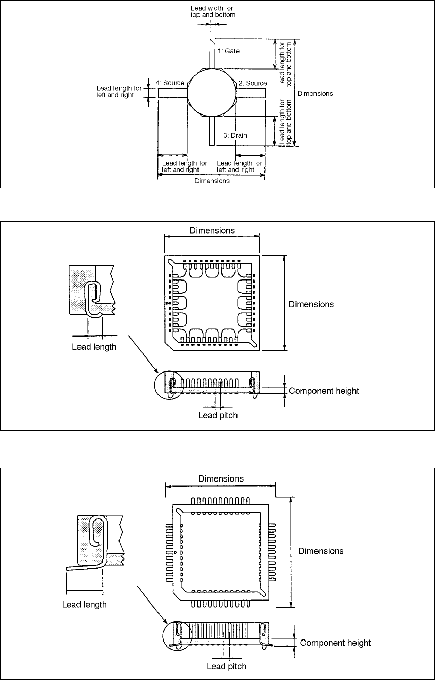
⑧ Aluminum electrolytic capacitor (Bottom view)
5 − 4
⑨ GaAsFET (Top view)
⑩ J lead socket (Top view)
⑪ Gull wing socket (Top view)