4OM-1343-009_w.pdf - 第119页
1-60-3 AKFEMT -ID (5) Shakeitintherotationaldirectionandconrmthattheitdoesnot rotate. Afterthat,pulloutthelterreplacementjigcarefullysoas nottopulluptheinsertedltertogetherandstaya…
1-60-2
AKFEMT-ID
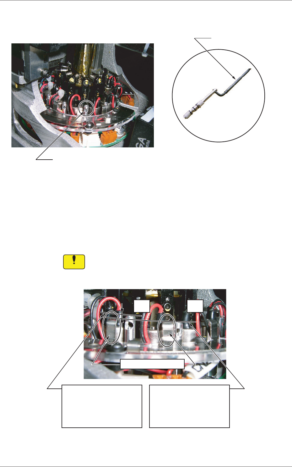
(2) Insertthelterreplacementjigintotheholeonthelterholderand
pull it up upward.
Hole on Filter Holder
Jig with pulled-out holder (filters)
Filter Replacement Jig
Fig. 4A62
(3) Replacethetwovacuumltersonthepulled-outholderwithnew
ones.
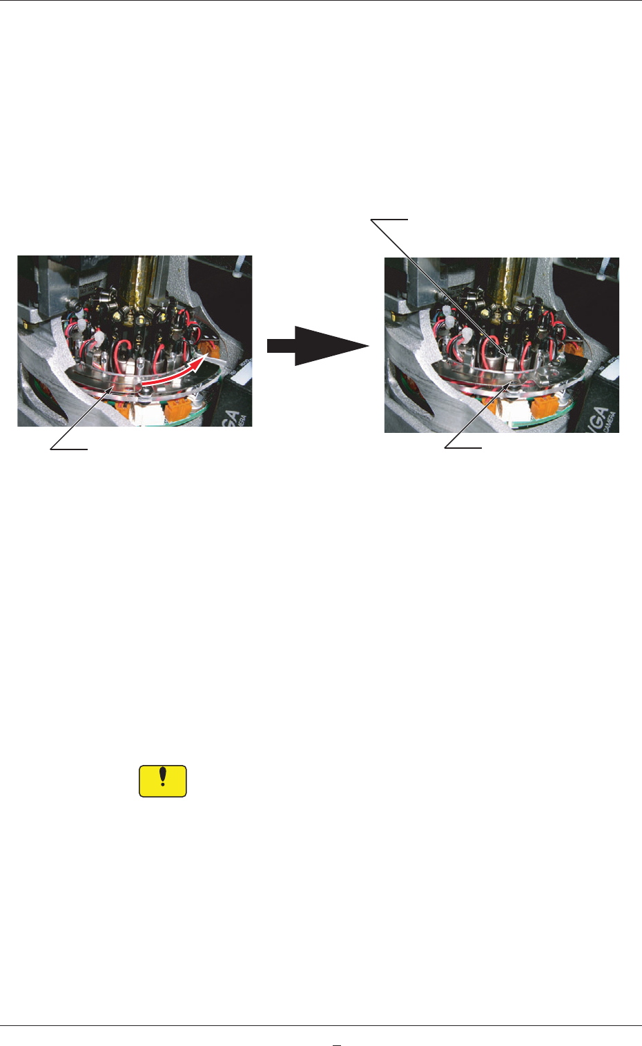
(4) Directthelargerholeon
thelterholderoutwardandinsertthe
holderwiththelterreplacementjig.
Be sure to push it deep enough until it stops (down to the lowest
limit).
Notice
The holder should not interfere with the wirings for valves, etc. In addition,
the wires should not be caught in the upper and lower areas of the top
block.
OK
NG
Filter Fastening Claw
<NG: Insufficient Insertion>
The upper surface of the
filter holder is higher than
that of the filter fastening
claw.
<OK: Sufficient Insertion>
The filter fastening claw is
higher than that of the filter
holder.
Fig. 4A63
0604-001
4.6 Replacement Procedure of Vacuum Filters
1-60-3
AKFEMT-ID
(5) Shakeitintherotationaldirectionandconrmthattheitdoesnot
rotate.Afterthat,pulloutthelterreplacementjigcarefullysoas
nottopulluptheinsertedltertogetherandstayaoat.
(6) Notethefollowingandslidethelterfastenertotherighttolock
thelterholder.
·
Conrmthatthelterfasteningclawislocatedattheupper
centerofthelterholder.
·
Conrmthat
theballplungerislocked.
Slide the filter fastener to the right.
Filter Unlocked Filter Locked
Locking Position of Filter
Fastening Claw
Ball Plunger Locked
Fig. 4A64
Whenthelterfasteningclawcannotbelockedafterbeingslid
becauseitinterfereswiththesidefaceofthelterholder,itcan
beassumedthataforeignsubstanceexistsintheholeorthelter
holderisnotinsertedsufcientlyfarintothehole.
Checkthelterholderthathasinterferedwiththesideface.Ifa
foreignsubstanceexistsinthehole,cleanthelterholdertoremove
the substance.
After the cleaning is completed and no foreign substance is found in
the hole, starting with Step (4).
Notice
Unlessthelterholderissetcorrectlyinplace,apickuperrorwilloccur
orthelterwillcomeoffandcauseaninterferencewithahead.Thehead
may also be damaged.
0604-001
4.6 Replacement Procedure of Vacuum Filters

AKFEMT-ID
0909-005
5. Consumables and Important Servicing Parts
1-61
5. Consumables and Important Servicing Parts
5.1 List of Consumables
Listed below are the parts that may be consumed within one year.
Consult our marketing department or sales agency whenever you need to
purchase these parts.
Table 4A14
Product Name Part No. Part Name Q'ty
Recommended
Q'ty/Years Note (a)
Exploded
View
Remarks
Nozzle (HV31) 016M1433
(630 152 8267)
ASSY, NOZZLE (HV31) 48 48 Fig. SA-2
Nozzle (HV51) 016M1434
(630 152 8472)
ASSY, NOZZLE (HV51) 48 48
Nozzle (HV01) 016M0929
(630 129 2878)
ASSY, NOZZLE (HV01) 48 48
Nozzle (PV81) 016M1482
(630 158 9084)
ASSY, NOZZLE (PV81) 48 48
Nozzle (HV02) 016M0930
(630 129 2885)
ASSY, NOZZLE (HV02) 48 48
Nozzle (HV03) 016M0931
(630 129 2892)
ASSY, NOZZLE (HV03) 48 48
Nozzle (HB03) 016M0932
(630 129 2908)
ASSY, NOZZLE (HB03) 48 48
Nozzle (HB04) 016M0933
(630 129 2915)
ASSY, NOZZLE (HB04) 48 48
Nozzle (HA04) 016M0934
(630 129 2922)
ASSY, NOZZLE (HA04) 48 48
Nozzle (HA05) 016M0935
(630 129 2939)
ASSY, NOZZLE (HA05) 48 48
Nozzle (HA09) 016M0936
(630 129 2946)
ASSY, NOZZLE (HA09) 48 48
Nozzle (PA05) 016M1074
(630 133 5407)
ASSY, NOZZLE (PA05) 48 48
Nozzle (PA07) 016M2168
(630 135 0295)
NOZZLE (PA07) 48 48
Vacuum Filter 225B0508
(630 126 9252)
AIR LINE EQPT 96 384 Fig. M-6
Fig. SA-1
Fluorine Sheet 212A2219
(630 136 6906)
GUIDE 4 4 Fig. DC-1
Fig. DD-1
Urethane Clamp 226J2299
(630 149 5804)
226J2403
(630 158 0340)
MECH, PARTS 4
4
4
4
Fig. DC-4
Fig. DD-4
Flat Ring 226A0256
(630 137 6028)
SEAL 4 16 Fig. DC-3
Fig. DD-3
For Roller on
Oscillating
Side in Cutter
Section
Cutter Blade 213D1294
(630 157 9795)
DISK 8 8 Fig. DC-3
Fig. DD-3
Note (c)