00197288-02_AI_TBO_SX12_V2_DE_EN.pdf - 第38页
1 Introduction 1.2 Preparatory work... 38 Assembly Instructions / Montageanleitung SIPLACE SX1/SX2 V2 Thick Board Option Option Dicke Leiterplatte 02/2019 ► Isolate the machine from all its energy sources: ð Shut off the…
1 Introduction
1.2 Preparatory work...
Assembly Instructions / Montageanleitung SIPLACE SX1/SX2 V2 Thick Board Option Option Dicke Leiterplatte
02/2019
37
1.1.7 Classification of the optical systems
1.1.7.1 Classification of the whole machine
Fig.2: Laser class 2
The ready-to-operate overall machine is assigned
to laser class°2.
The laser classes are determined according to
DIN EN 60825-1:2014.
1.1.7.2 Laser classification
The following modules are assigned to laser class 2:
●
Component sensor on the SpeedStar
●
Component sensor on the MultiStar
●
Laser light barriers at the board conveyor
1.1.7.3 Classification of the camera systems
WARNING
LEDs
The camera illumination systems are fitted with light LEDs. These are assigned to risk
group 1 according to IEC 62741:2006.
► Do not look into beam!
1.2 Preparatory work...
Purpose and scope
Before performing any preventive maintenance work, conversion work or service work, a procedure
of locking and tagging must be followed and warning signs must be attached if not stated other-
wise. If it is not necessary to switch off the machine, it is explicitly mentioned.
The procedure, when followed correctly as described in this section, eliminates the possibility of an
employee being injured.
NOTICE
Additional safety measures
This procedure represents the minimum lock out and tag out requirements for the machine
during preventive maintenance work and service work. Any additional safeguards needed
to complete work safely can be specified by facilities supervision, the safety officer, the
safety committee and the health department.
Description
Whenever it becomes necessary to isolate, control and release energy, the following procedure is
to be followed.
► Notify all affected employees.
► Switch off the machine and all additional devices. Carry out all normal stopping procedures:
ð Press the STOP button.
ð Shut down the station computer.
ð Switch off the machine using the main switch.
1 Introduction
1.2 Preparatory work...
38 Assembly Instructions / Montageanleitung SIPLACE SX1/SX2 V2 Thick Board Option Option Dicke Leiterplatte
02/2019
► Isolate the machine from all its energy sources:
ð Shut off the compressed air supply.
ð Shut off the main power supply.
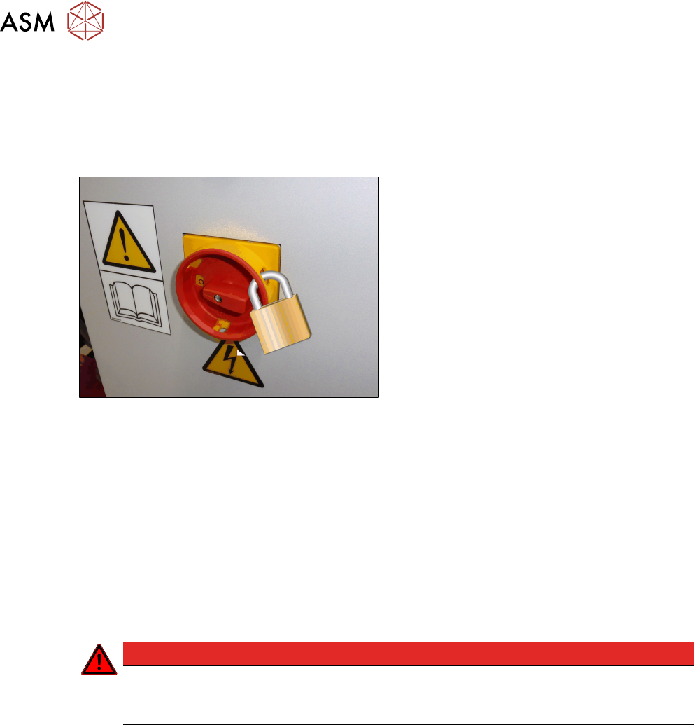
► Lock out the machine.
ð Attach a lock wherever possible.
Fig.3: Attaching a padlock to the main power switch
Secure main switch
► Secure the main switch with a padlock.
► Alternatively, you can attach warning signs:
Any machine that can be locked must be locked.
However, there are situations where energy isolating devices cannot accommodate locks. In
these cases, the energy isolating devices must be tagged appropriately to warn employees
that the machine is currently de-energized for service purposes. The tag or label must be
fastened securely in a position visible from all sides and it may only be removed by the person
who attached it.
► Release of stored energy:
Energy stored as compressed air in the compressed air supply or electrical energy stored in
electrolytic capacitors must be released by appropriate means.
After switching off the machine, wait until the voltages have discharged and the compressed
air has released, so that work can be performed without any risk.
DANGER
Checking for absence of voltage!
► Before you start working, check the power supply for absence of voltage and observe
the waiting times!
► Testing the lock out:
The lock can be easily tested by pressing the START button.
The following steps must be taken to restore the machine to operation.
► Check the workspace. Authorized employees should remove all of their tools and reinstall all
safety features.
► Notify all affected employees.
► Before removing even one lock or tag, inform all workers in the affected area that the machine
is going to be restarted.
► Remove all locks/tags.
Every authorized employee must remove his own lock and shut it away.
► Turn the machine on. Make sure that authorized staff check the equipment in operation to en-
sure that all repairs were performed correctly.
1 Introduction
1.3 Other instructions
Assembly Instructions / Montageanleitung SIPLACE SX1/SX2 V2 Thick Board Option Option Dicke Leiterplatte
02/2019
39
Testing
Service personnel may test circuits by energizing them briefly without suspending the Lock Out /
Tag Out Procedure. This may only be done when no other work is being performed by any other
person on the equipment being tested.
It is extremely important that all remote START switches are tagged with the "Do Not Operate" tag
to prevent inadvertent operation of the equipment during these periods.
Responsibilities
●
It shall be the responsibility of the maintenance and service personnel to make sure this pro-
cedure is adhered to.
●
It shall be the responsibility of the maintenance and service personnel's immediate supervisor
to instruct their personnel on this procedure.
●
It shall be the responsibility of the Safety Officer to administer the Lock Out / Tag Out Proced-
ure.
1.3 Other instructions
1.3.1 Environmentally-friendly disposal of materials and components
Our products are manufactured using only materials and parts that can be easily separated and
disposed of in an environmentally-friendly way.
NOTICE
Observe the applicable regulations
The company operating the system has sole responsibility for the proper, environmentally-
friendly disposal of machines, working materials, consumable materials and wear parts.
► Please observe your national statutory provisions for waste disposal and environ-
mental protection.
1.3.2 Use of original accessories and spare parts
Only use original spare parts and authorized accessories. The use of other parts will affect safety
and will invalidate the liability for any consequential damage.
1.3.3 ESD guidelines
1.3.3.1 What does ESD mean?
Fig.4: ESD label
Almost all of the modules in use today are equipped with highly integ-
rated Metal-Oxide-Semiconductor (MOS) blocks and components.
The manufacturing techniques used mean that these electronic com-
ponents are extremely sensitive to overvoltage and thus to electro-
static discharge.
The abbreviation for such modules is "ESD" (Electrostatic Sensitive
Device). "ESD" is used internationally. The following symbol on cab-
inet rating plates, racks or packaging indicates that components
which are sensitive to electrostatic discharge have been used and
thus that the modules concerned are also touch-sensitive.
ESDs can be destroyed by voltages and power levels that are far below the level that can be per-
ceived by humans. Such voltages occur if a person touches a component or module without
earthing themselves. Components that are exposed to such overvoltages do not generally appear
to be defective immediately - incorrect behavior starts after the component or module has been in
operation for some time.