00197288-02_AI_TBO_SX12_V2_DE_EN.pdf - 第47页
3 Installation 3.3 Lowering the Conveyor Assembly Instructions / Montageanleitung SIPLACE SX1/SX2 V2 Thick Board Option Option Dicke Leiterplatte 02/2019 47 ► Switch off the machine, disconnect it from the power supply a…
3 Installation
3.2 Preparatory Steps
46 Assembly Instructions / Montageanleitung SIPLACE SX1/SX2 V2 Thick Board Option Option Dicke Leiterplatte
02/2019
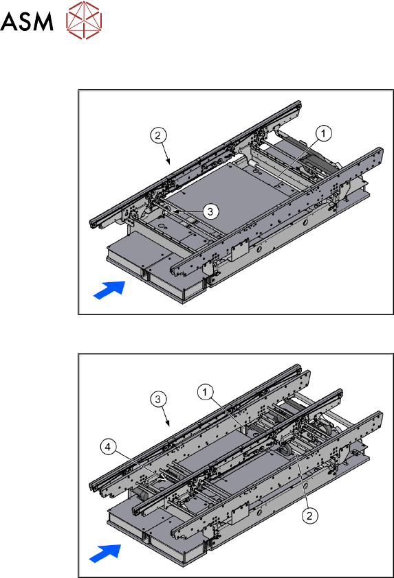
3.1.3 Width Adjustment
Fig.7: Width adjustment for single conveyor
1. Recirculating spindle
2. Toothed belt of width adjustment
3. Drive unit of width adjustment
Fig.8: Width adjustment for dual conveyor
1. Adjustment unit
2. Recirculating spindle
3. Toothed belt of width adjustment
4. Drive unit of width adjustment
Function description
The width is adjusted by means of a motor as programmed. For dual conveyor systems, differing
widths can be set for the two conveyor lanes. The width adjustment uses a motor with its own
measuring system, meaning that the PCB width can be set independently of other machine com-
ponents (e.g. the Y gantry).
The PCB width is adjusted using two width adjustment units, which are fitted in the input and output
areas. These adjustment units are moved synchronously back and forth by the drive motor, with
the help of recirculating spindles and a toothed belt.
In the dual conveyor, the fixing pins are moved out to release the clamp of the side rail. At the
same time, the side rail is fixed to the adjustment unit. After reaching the new PCB width, both fix-
ing pins move back in. The side rail is then clamped again.
In the single conveyor, the flexible rail is moved directly by the two recirculating spindles of the
adjustment units.
3.2 Preparatory Steps
► Use the software to move the conveyor sides into the position which allows you best access.
We recommend the following setting for this:
Set the two outer sides to their outermost positions at 281mm (dual) and the lane width to
160mm. The conveyor sides are then distributed as equally as possible across the conveyor
for best accessibility.
Alternatively, you can also loosen the conveyor side clamps on the dual conveyor. Read the
service manual for your machine first.
► Move the component trolley out of the machine.
3 Installation
3.3 Lowering the Conveyor
Assembly Instructions / Montageanleitung SIPLACE SX1/SX2 V2 Thick Board Option Option Dicke Leiterplatte
02/2019
47
► Switch off the machine, disconnect it from the power supply and secure it to prevent unauthor-
ized reactivation. Observe the instructions in section 1.2 "Preparatory work..." [}37].
3.3 Lowering the Conveyor
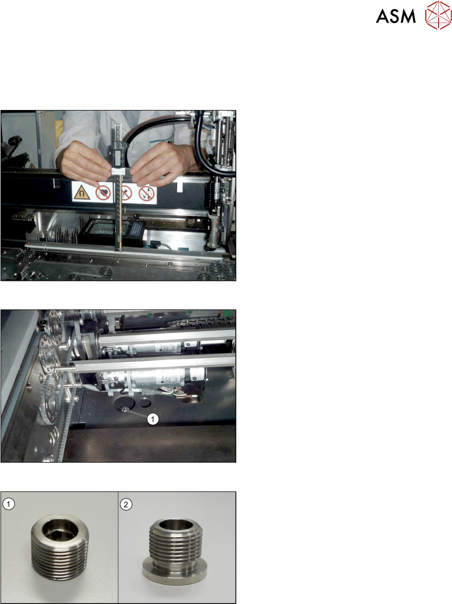
Fig.9: Checking the conveyor height
► Push the gantry over the conveyor.
► Check the height of the conveyor.
To do this, use a thickness gauge to
measure the distance from the upper
edge of the gantry to the clamping rails
and belt guidances.
Perform this measurement at the four
corners of the conveyor and the center
of the clamping rails.
This distance will be 176+/‑0.2mm in
SX1/SX2 V2 machines (see also 4.1
"Measurement Log" [}53]).
Fig.10: Fastening screw
► Remove the four fastening screws(1)
of the conveyor (Allen6). Remove the
screws and their washers.
You may need to dismantle the lifting
table plates to do this. Read the service
manual for your machine first.
These fastening screws are replaced with
longer ones during installation.
The setting screws for adjusting the con-
veyor height are located underneath the
fastening screws (Allen key size 10).
Fig.11: Setting screws
The setting screws fitted may vary according
to your conveyor version. If grub setting
screws without collar(1) are used, replace
these with setting screws which have a col-
lar(2) [03104139‑xx].
To do so, proceed as follows:
► Turn all four setting screws evenly upwards by one rotation. Repeat this until the conveyor
lays on the machine frame at all points.
► Now remove the old setting screws.
► Insert the new setting screws and tighten loosely to begin with.
Before you insert the screws, clean the area around them. Even minor contamination can in-
fluence the conveyor height.
3 Installation
3.3 Lowering the Conveyor
48 Assembly Instructions / Montageanleitung SIPLACE SX1/SX2 V2 Thick Board Option Option Dicke Leiterplatte
02/2019
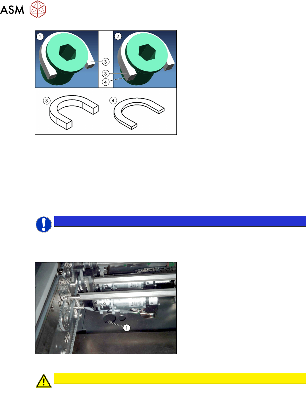
Fig.12: Grub screw with distance plates
1. Grub screw with collar and a distance
plate (5mm) for the standard height
2. Grub screw with collar and two dis-
tance plates (5mm and 2mm) for the
"Thick Board "option.
3. Horseshoe-shaped 5 mm distance
plate [03104924‑xx] (for standard and
"Thick Board" option)
4. Horseshoe-shaped 2mmm distance
plate [03104937‑xx] (for "Thick Board"
option only)
► Place one horseshow-shaped 5mm distance plate (standard height) und one horseshoe-
shaped 2mm distance plate (for "Thick Board" option) under the collar of each of the all set-
ting screws.
Now tighten all setting screws until they only just clamp the distance plates but do not yet al-
ter the conveyor height.
► Now turn all setting screws one rotation more so that the conveyor is raised equally at all
points.
Repeat this until the setting screws are tight.
NOTICE
Direction of rotation
► Turn the setting screws clockwise to move the conveyor upwards.
► Turn the setting screws anticlockwise to move the conveyor downwards.
Fig.13: Fastening screw
► Insert the new, long fastening
screws(1) incl. old washers and tighten
these.
Before you insert the screws, clean the
area around them. Even minor contam-
ination can influence the conveyor
height.
CAUTION
Have you fitted everything?
► Make sure that all eight U-shaped distance plates (4 x 2mm and 4x 5mm) are fitted.
If these are not all fitted, the machine could be damaged due to the conveyor being
too high.