00198328-01_AI_Basic Pack Vakuum Tooling_TX_DE_EN.pdf - 第55页
3 Installation 3.2 Assembly Montageanleitung / Assembly Instructions SIPLACE TX-Serie Basic Pack Vacuum Tooling 07/2017 55 ► Fit the two vacuum switches (1) into the plate supports. ► Connect the two PUN 6 - 800 mm pneum…
3 Installation
3.2 Assembly
54 Montageanleitung / Assembly Instructions SIPLACE TX-Serie Basic Pack Vacuum Tooling 07/2017
3.2 Assembly
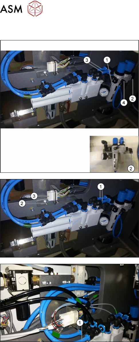
► Fit the angle with the maintenance unit (1).
► Connect the pneumatic hose for the compressed
air supply of the maintenance unit (2).
► Connect the two PUN 10 - 70 mm pneumatic
hoses (3) to the maintenance unit.
► Connect the manometer output (4) to the mano-
meter: Connect the PUN 6 - 300 mm pneumatic
hose to the manometer output (4). Connect the
hose from the back to the manometer beside (1).
► Connect the vacuum unit to the maintenance unit
via the two pneumatic hoses (1).
► Fit the angle with the vacuum unit (2) at the side
wall as displayed in the picture.
► Pull the [03139108-04] cable through the opening
inside the machine through the side panel.
► Fit the connector (3) in the bracket (connector
X34.VT with cable [03139108-04]).
► Connect the 2 tied PUN 8 - 2800 mm pneumatic
hoses (1) to the T-pieces of the vacuum unit. The
ends shall then be drawn through the machine to
below the conveyor unit, please refer to the sub-
sequent illustrations and description.
3 Installation
3.2 Assembly
Montageanleitung / Assembly Instructions SIPLACE TX-Serie Basic Pack Vacuum Tooling 07/2017 55
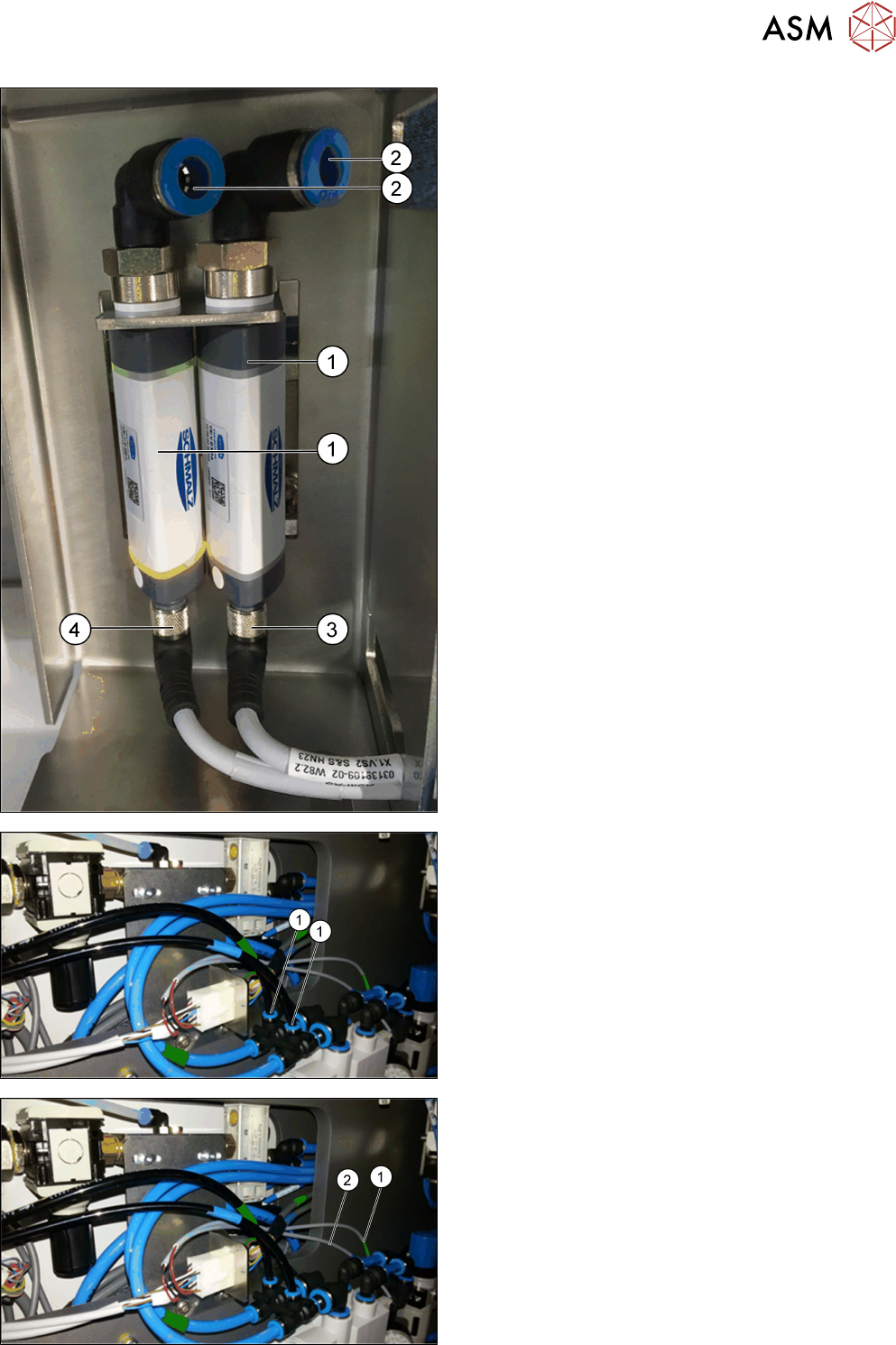
► Fit the two vacuum switches (1) into the plate
supports.
► Connect the two PUN 6 - 800 mm pneumatic
hoses to the opening (2) at the vacuum switch
(1). Observe the green marking for lane 1 and the
blue marking for lane 2!
► Connect the X1.VS2 cable (3) to the right va-
cuum switch.
► Connect the X1.VS1 cable (4) to the left vacuum
switch.
► Pull down the pneumatic hoses and the cables
through the corner cover.
► Connect the two pneumatic hoses to the vacuum
unit (1). Observe the green marking for lane 1
and the blue marking for lane 2!
► Connect the X1.Y1 cable (1) to the left valve of
the vacuum unit (green marking for lane 1).
► Connect the X1.Y2 cable (2) to the right valve of
the vacuum unit (blue marking for lane 2).
3 Installation
3.2 Assembly
56 Montageanleitung / Assembly Instructions SIPLACE TX-Serie Basic Pack Vacuum Tooling 07/2017
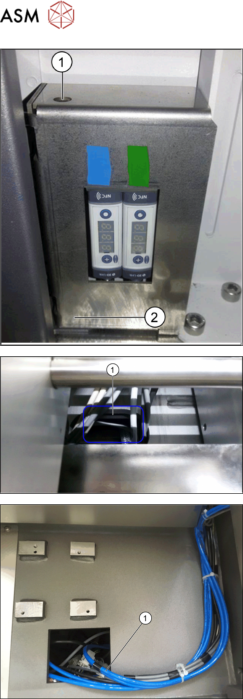
► Fit the corner cover together with the vacuum
switch support!
The screw is behind the plate (2). Tighten the
screw of the corner cover via the access to the
screw (1).
► Remove the conveyor cover.
► Pull the [03139108-04] cable through the side
panel into the machine and through the opening
in the machine base (1) to below the conveyor.
► Pull through the two tied PUN 8 - 2800 mm pneu-
matic hoses (1) through the machine to the open-
ing at location 1 for the feeder location.
► Then pull through the hoses and cables to the va-
cuum tooling cover.