00198328-01_AI_Basic Pack Vakuum Tooling_TX_DE_EN.pdf - 第66页
3 Installation 3.3 Final Work 66 Montageanleitung / Assembly Instructions SIPLACE TX-Serie Basic Pack Vacuum Tooling 07/2017
3 Installation
3.3 Final Work
Montageanleitung / Assembly Instructions SIPLACE TX-Serie Basic Pack Vacuum Tooling 07/2017 65
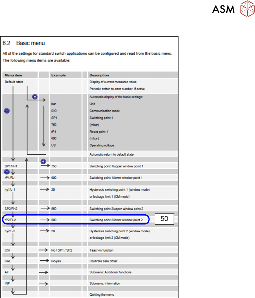
3.3.1.6 Setting Hysteresis Switching Point 2
Fig.9: Setting hysteresis switching point 2
Proceed as follows to set hysteresis switching point 2:
► Press the SET button.
► Press the SET button until you see the rP2 (Hysteresis 2) menu item.
► Press the MODE button. A value appears on the display. The one point flashes.
► Press the SET button and set a value 0-9.
► Press the MODE button. The tens point flashes.
► Press the SET button and set a value 0-9.
► Press the MODE button. The hundreds point flashes.
► Press the SET button and set a value 0-9.
► The display shall now show 50.
► Wait 2 seconds. rP2 appears on the display again.
► Quit the menu.

3 Installation
3.3 Final Work
66 Montageanleitung / Assembly Instructions SIPLACE TX-Serie Basic Pack Vacuum Tooling 07/2017
4 Appendix
4.1 Excerpts from the Service Manual
Montageanleitung / Assembly Instructions SIPLACE TX-Serie Basic Pack Vacuum Tooling 07/2017 67
4 Appendix
4.1 Excerpts from the Service Manual
The following chapters are excerpts from the service manual for your machine. If required, further
information is provided there.
●
Service Manual SIPLACE TX-Series [DE:00198149‑xx] [EN:00198150‑xx]
4.2 Circuit Diagrams
For more information, refer to the circuit diagrams folder:
●
Detailed circuit diagrams folder for SIPLACE TX-Series (up to no. 499) [DE+EN: 00197933-
xx]
●
Detailed circuit diagrams folder for SIPLACE TX-Series (from no. 500) [DE+EN: 00198274-xx]
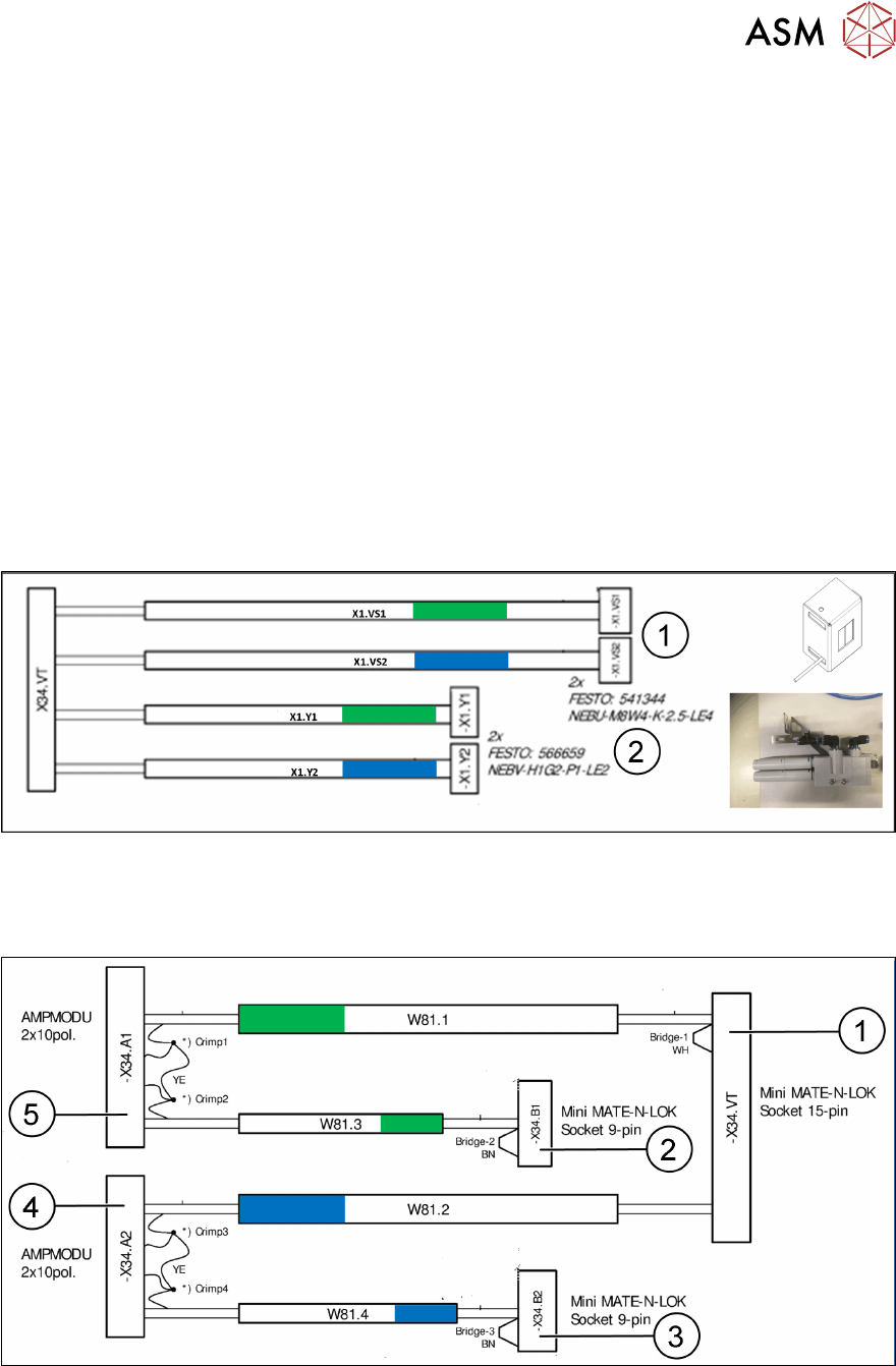
4.3 Cable Overview
4.3.1 Connectors Location 2
1. Connectors to vacuum switch at the corner cover
2. Connectors to valves for vacuum distribution
4.3.2 X34 Connectors Conveyor Control
1. Socket at the side of location 2
2. Socket lane 1 in the plate below conveyor lane 1
3. Socket lane 2 in the plate below conveyor lane 2
4. X34 connector conveyor control lane 2
5. X34 connector conveyor control lane 1