00198328-01_AI_Basic Pack Vakuum Tooling_TX_DE_EN.pdf - 第58页
3 Installation 3.3 Final Work 58 Montageanleitung / Assembly Instructions SIPLACE TX-Serie Basic Pack Vacuum Tooling 07/2017 ► Fit the cover plate (1) at the machine base. NOTICE Input pressure manometer Set the manomete…
3 Installation
3.3 Final Work
Montageanleitung / Assembly Instructions SIPLACE TX-Serie Basic Pack Vacuum Tooling 07/2017 57
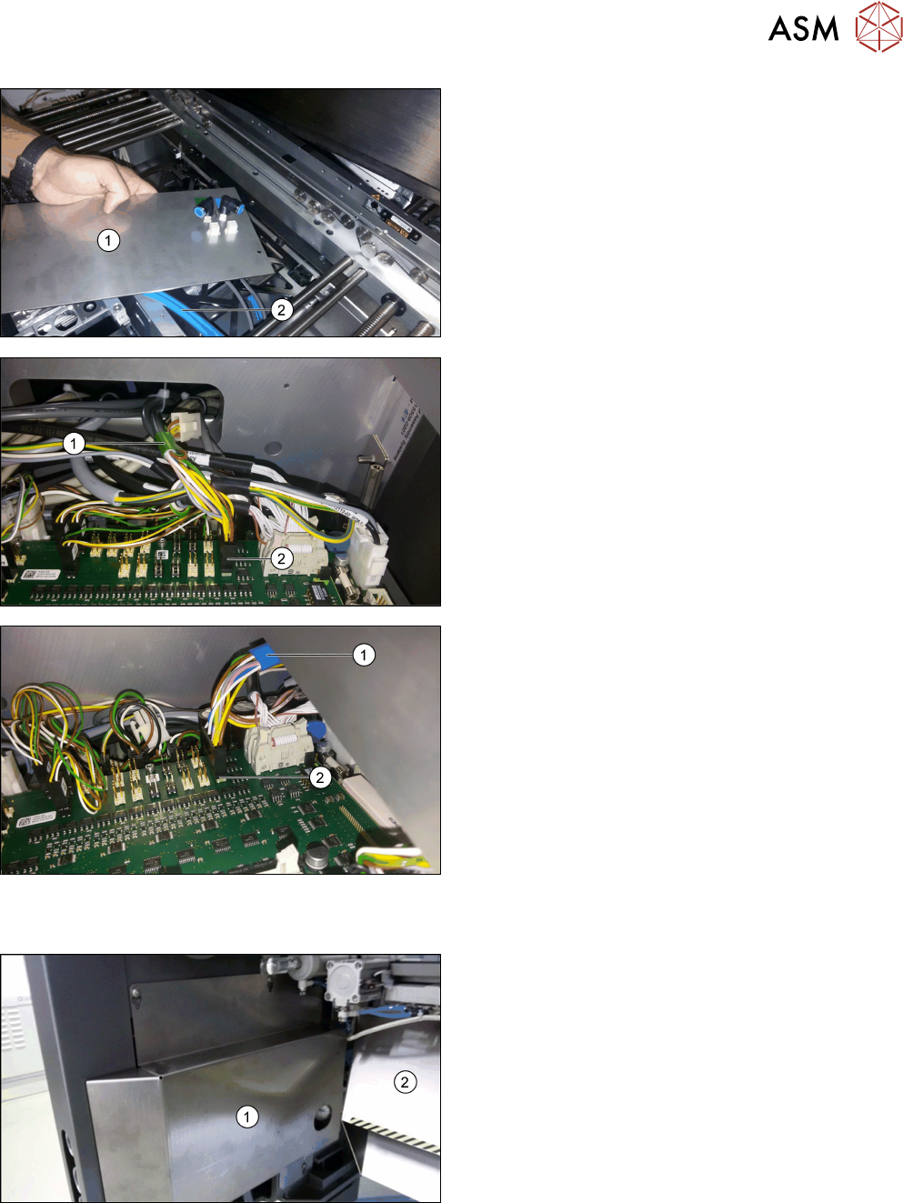
► Fix both connectors from below to the vacuum
tooling cover [03149358-xx] (1).
► Connect both vacuum hoses (2) from below to
the vacuum tooling cover.
Observe the green marking for lane 1 and the
blue marking for lane 2!
► Fit the vacuum tooling cover in the output area of
the conveyor.
► Connect the vacuum toolings from above.
► Dismantle both cover plates via the conveyor
controls.
► Cable connection to the conveyor control lane 1
(green marking (1)):
Connect the [03139108-04] cable to the X34.A1
connector (2) at TSPcontrol board Lane 1 - X34.
► Cable connection to the conveyor control lane 2
(blue marking (1)):
Connect the [03139108-04] cable to the X34.A2
connector (2) at TSPcontrol board Lane 2 - X34.
3.3 Final Work
► Refit all covers in the conveyor area.
► Fit the new slide plate (1) and the waste tape
chute (2).
3 Installation
3.3 Final Work
58 Montageanleitung / Assembly Instructions SIPLACE TX-Serie Basic Pack Vacuum Tooling 07/2017
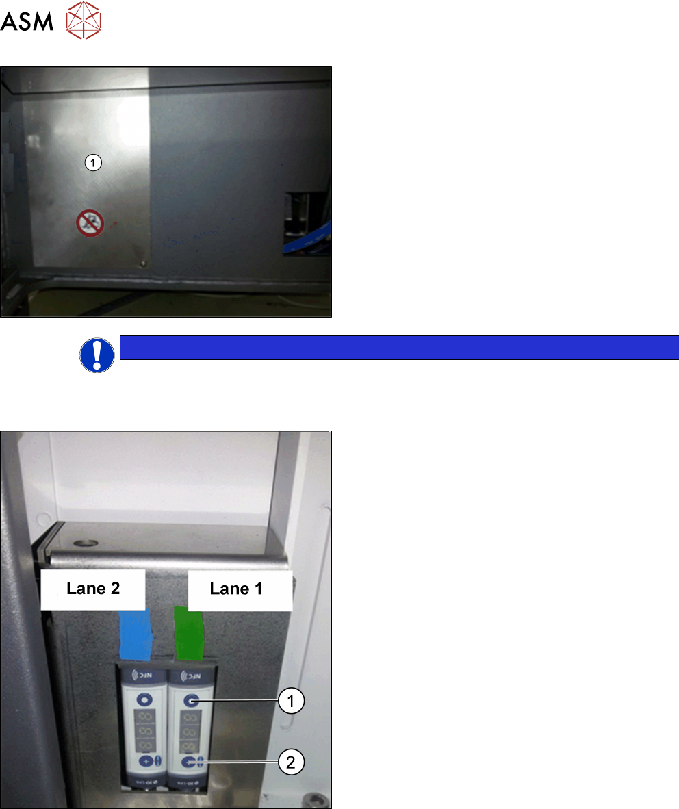
► Fit the cover plate (1) at the machine base.
NOTICE
Input pressure manometer
Set the manometer of the maintenance unit to an input pressure of 3.5 bar (max. permiss-
ible are 4.2 bar).
► Setting of the vacuum switches: At a vacuum of
0.1 bar (100 mbar) with a hysteresis of 0.05 bar
(50 mbar), the lifting table should sink.
At 0.45 bar (450 mbar) with a hysteresis of 0.05
bar (50 mbar), the placement should start.
► Perform the setting with the MODE button (1) and
SET button (2); please refer to the enclosed
Schmalz instructions for the vacuum switch
[30.30.01.00997/1 - 04.2016].
3 Installation
3.3 Final Work
Montageanleitung / Assembly Instructions SIPLACE TX-Serie Basic Pack Vacuum Tooling 07/2017 59
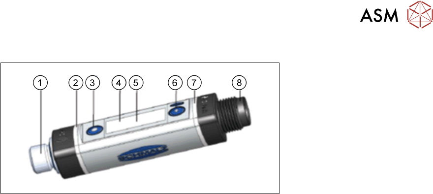
3.3.1 Settings in the Vacuum Switch
Fig.4: Vacuum switch
1. Fluid connection
2. Switching point 1 display, ORANGE or operating voltage display, GREEN
3. MODE button
4. Display
5. Position of the NFC antenna behind the display
6. SET button
7. Switching point 2 display, ORANGE
8. Electrical connection M12-4 or M8-4
Basic operation:
●
Press the SET button for the basic menu.
●
To scroll forward, press the SET button.
●
To select a menu item, press the MODE button.
You can quit or cancel the menus as follows:
●
Press both SET and MODE buttons.
●
Do not press any button for 1 minute.