00198328-01_AI_Basic Pack Vakuum Tooling_TX_DE_EN.pdf - 第59页
3 Installation 3.3 Final Work Montageanleitung / Assembly Instructions SIPLACE TX-Serie Basic Pack Vacuum Tooling 07/2017 59 3.3.1 Settings in the Vacuum Switch Fig.4: Vacuum switch 1. Fluid connection 2. Switching poin…
3 Installation
3.3 Final Work
58 Montageanleitung / Assembly Instructions SIPLACE TX-Serie Basic Pack Vacuum Tooling 07/2017
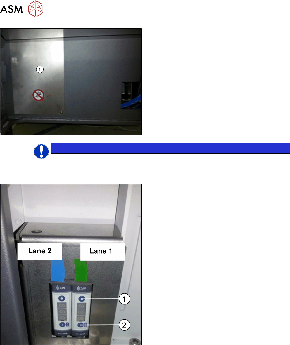
► Fit the cover plate (1) at the machine base.
NOTICE
Input pressure manometer
Set the manometer of the maintenance unit to an input pressure of 3.5 bar (max. permiss-
ible are 4.2 bar).
► Setting of the vacuum switches: At a vacuum of
0.1 bar (100 mbar) with a hysteresis of 0.05 bar
(50 mbar), the lifting table should sink.
At 0.45 bar (450 mbar) with a hysteresis of 0.05
bar (50 mbar), the placement should start.
► Perform the setting with the MODE button (1) and
SET button (2); please refer to the enclosed
Schmalz instructions for the vacuum switch
[30.30.01.00997/1 - 04.2016].
3 Installation
3.3 Final Work
Montageanleitung / Assembly Instructions SIPLACE TX-Serie Basic Pack Vacuum Tooling 07/2017 59
3.3.1 Settings in the Vacuum Switch
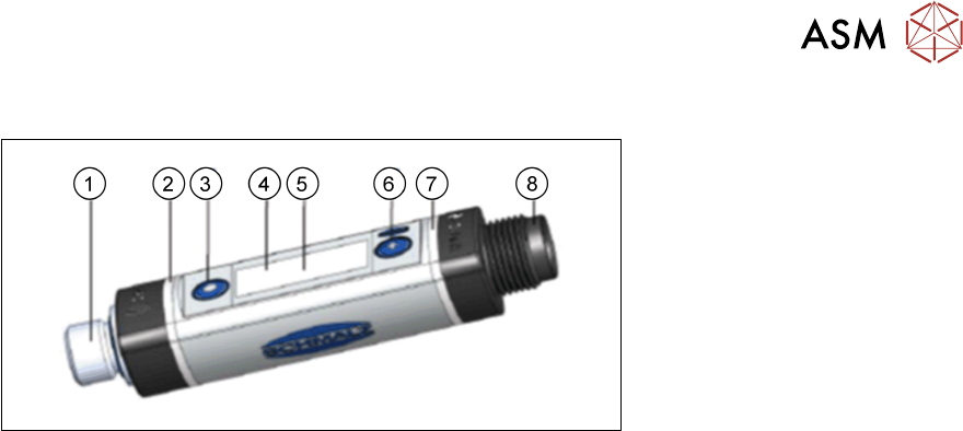
Fig.4: Vacuum switch
1. Fluid connection
2. Switching point 1 display, ORANGE or operating voltage display, GREEN
3. MODE button
4. Display
5. Position of the NFC antenna behind the display
6. SET button
7. Switching point 2 display, ORANGE
8. Electrical connection M12-4 or M8-4
Basic operation:
●
Press the SET button for the basic menu.
●
To scroll forward, press the SET button.
●
To select a menu item, press the MODE button.
You can quit or cancel the menus as follows:
●
Press both SET and MODE buttons.
●
Do not press any button for 1 minute.

3 Installation
3.3 Final Work
60 Montageanleitung / Assembly Instructions SIPLACE TX-Serie Basic Pack Vacuum Tooling 07/2017
3.3.1.1 Factory Settings
Parameter VSi-V VSi-P10 VSi-VP8
Switching point 1
Switching point mode and logic Two-point mode, normally closed (H.
no)
Switching point SP1 750 mbar 5500 mbar -750 mbar
Reset point rP1 600 mbar 5000 mbar -600 mbar
Window hysteresis Hy1 / leakage limit per sec L-1 20 mbar 100 mbar 20 mbar
Switch-on delay dS1, switch-off delay dr1 0ms 0ms 0ms
Switching point 2
Switching point mode and logic Two-point mode, normally closed (H.
no)
Switching point SP2 550 mbar 5000 mbar 5500 mbar
Reset point rP2 500 mbar 4500 mbar 5000 mbar
Window hysteresis Hy2 / leakage limit per sec L-2 20 mbar 100 mbar 20 mbar
Switch-on delay dS2, switch-off delay dr2 0ms 0ms 0ms
Transistor function PNP PNP PNP
Display unit mbar mbar mbar
Eco mode Off Off Off
Display alignment Standard Standard Standard
IO link device locks, extended device locks 0 0 0
Menu PIN code, NFC PIN code 000 000 000