TM4807.Long Board Partition Mount.pdf - 第5页
4 De ta il 4.1 Movement of machine 4.1.1 T ransfer method and mount method In this function, the partition mount is executed in the following procedures. (1) A board is transferred to the main stopper; the b oard is fixe…
3.2 Restrictions on the board data for long board partition
mount
1. Values of X coordinate and R coordinate of block offset have to be “0.000”. (Ref. 4.2.3)
2. One set of board fiducial is required for the position that can be recognized at “first half
mount”, and another one set of board fiducial is required for the position that can be
recognized at “second half mount”. (Ref. 4.2.3.1)
3. Block fiducial is not able to use. (Ref. 4.2.3.2)
4. The board bad mark and the block bad mark have to be recognizable at “first half mount”.
(Ref. 4.2.5)
5. Visual editor of P-Tool does not support board fiducial for “second half mount”. (Ref.
4.2.3.1)
6. This function does not support sequence running mode.
7. When using 2D code scan function (special function), all 2D code (board, block,
distributed) has to be recognizable at “first half mount”. (Ref. 4.2.6)
3.3 Restrictions when machine produces board data for long
board partition mount
1. Only “Line” or “Manual” can be used for “Conveyor Spec”.
2. “Precede Pick” is executed only before the starting of “first half mount”. It is not executed
before the starting of “second half mount”.
3. Cycle times and error counts of history are outputted total of “first half mount” and
“second half mount”. Each of “first half mount” and “second half mount” is not outputted.
(Ref. 4.5)
4 Detail
4.1 Movement of machine
4.1.1 Transfer method and mount method
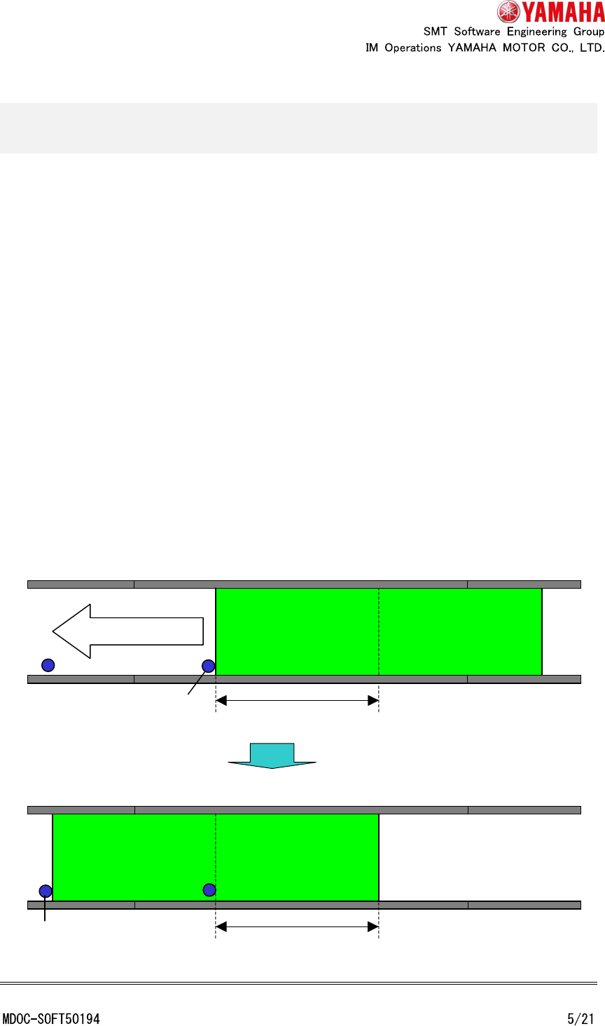
In this function, the partition mount is executed in the following procedures.
(1) A board is transferred to the main stopper; the board is fixed; and parts of first half area
are mounted.
(2) After parts of first half area are mounted, the board is released and transferred to the
exit stopper.
(3) After the board reaches the exit stopper, the board is fixed, and parts of second half
area are mounted.
(4) After parts of second half area are mounted, the board is released and transferred to
the lower machine.
(5) After the board is transferred to the lower machine, a next board is transferred from
entrance.
Case of first half area mount
Case of second half area mount.
Second half mount area
Exit stopper
First half mount area
Conveyor direction
Main stopper
* The next board is not carried in until the mounted board is carried out. When you insert a
board by manual, insert it when no board exists in the machine. If a board is inserted during
transfer, the board might be regarded as a part of transferring board and be overlapped.
4.1.2 Decision method of mount position for each mount
The mount position (“first half mount” or “second half mount”) of each mount data is
decided as follows.
Optimized or
unoptimized board data
Decision method of mount position (“first half mount” or
“second half mount”)
Optimized board data The mount position of each mount data is decided by
optimization.
Unoptimized board data Basically, the mount position of each mount data is uniformly
decided from the mount coordinates.
That is to say, all mount data that can be mounted at “first half
mount” are mounted at “first half mount” and the others are
mounted at “second half mount”.
But, when the local fiducial or the local bad mark is not
recognizable at “first half mount” even if the mount coordinate of
mount data can be mounted at “first half mount”, this mount is
mounted at “second half mount”.
4.1.3 Existence of “first half mount” parts and “second half mount” parts
and the movement
Existence of “first half mount” parts and “second half mount” parts and these movements
are as follows.
Board data type Movement
Both “first half mount” parts
and “second half mount” parts
exists
Both “first half mount” and “second half mount” are
executed.
There are restrictions of board data to be described below.
Only second half mount parts
exists
(Long boards which do not
have “first half mount” parts)
Only “second half mount” is executed. When it is necessary,
bad marks are recognized at the main stopper position.
There are restrictions of board data to be described below.