TR518_SII_硬体规格与架构_v1.0.0.pdf - 第20页
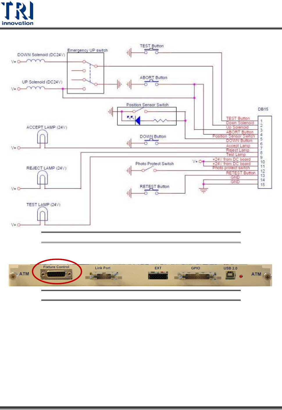
Test R esearch Inc. 18 TR518 SII 使用手冊 --- 硬體 規格與架構 Figure 6: Analog T est Module (ATM) Board --- Press Unit 介面 Figure 7: Press Unit 在 ATM board 上的位置
Test Research Inc.
TR518 SII 使用手冊---硬體規格與架構 17
3.2.26 Press Unit 介面
Press Unit Interface at ATM board
針位定義:
PIN
Signal Name
1
TEST_Button
2
Down_Solenoid
3
Up_Solenoid
4
ABORT_Button
5
Position_Sensor_Switch
6
DOWN_Button
7
Accept_Lamp
8
Reject_Lamp
9
Test_Lamp
10
+24V
11
+24V
12
Photo Protect Switch
13
RESET_Button
14
GND
15
GND
Test Research Inc.
18 TR518 SII 使用手冊---硬體規格與架構
Figure 6: Analog Test Module (ATM) Board --- Press Unit
介面
Figure 7: Press Unit
在
ATM board
上的位置
Test Research Inc.
TR518 SII 使用手冊---硬體規格與架構 19
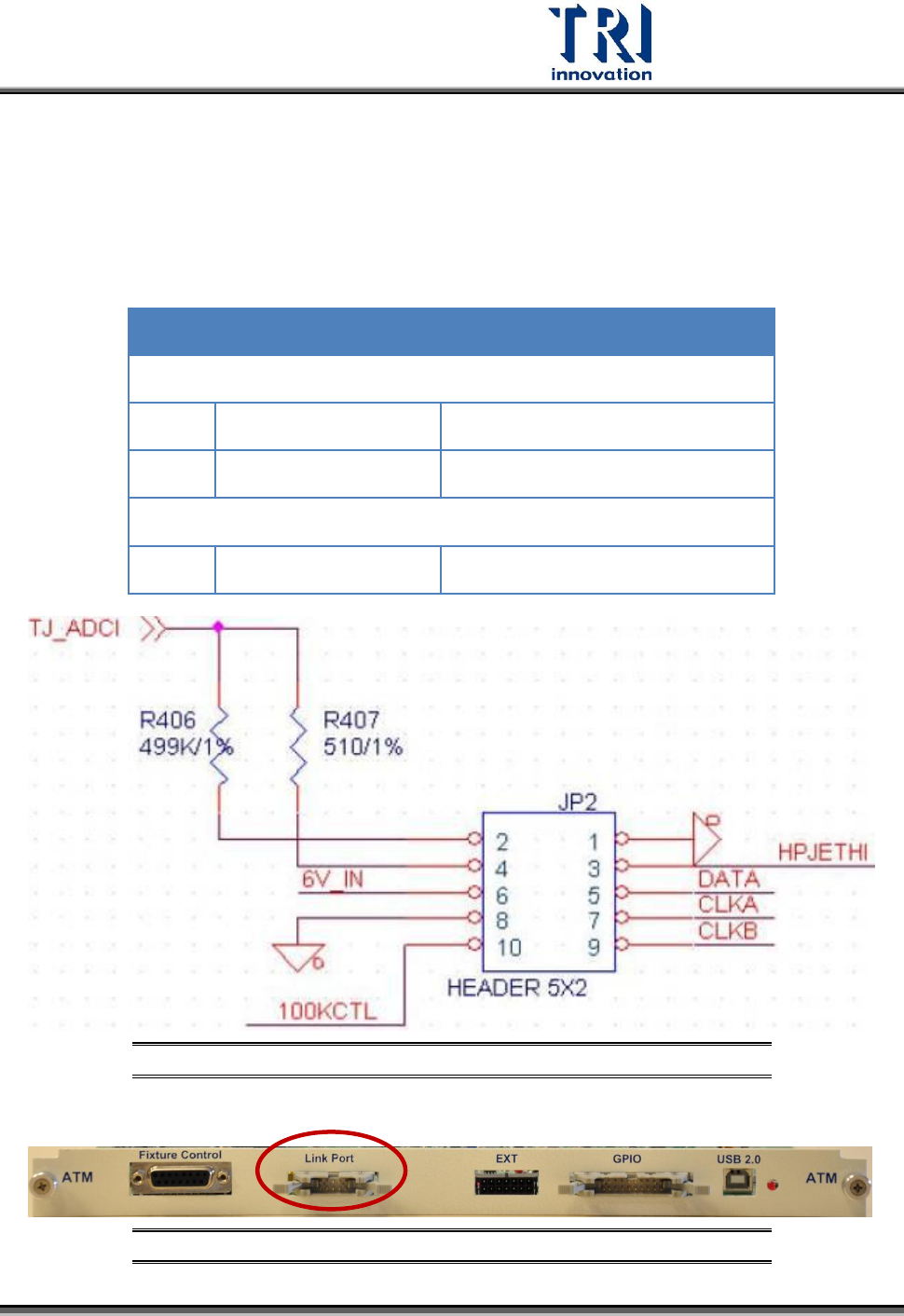
3.2.27 Link Port 介面
10-pin Interface 用來作為 ATM board 和 TestJet Card 之間的連接
針位定義:
PIN
Signal Name
PIN
Signal Name
1
GND
2
TJ_ADCI_Pull_High_499K
3
HPJETHI
4
TJ_ADCI_Pull_High_510
5
DATA
6
+6V
7
CLKA
8
GND
9
CLKB
10
100KCTL
Figure 7: Analog Test Module (ATM) Board --- TestJet
介面
Figure 9: Link Port
在
ATM board
上的位置