00193790-01.pdf - 第108页
2 English Installat ion and Getting Started with CACCIA 2.10 Overview of the J umper Settings for Individual Subsyst ems Issue 07/2004 42 2.10. 2 S IPLACE HF3: Description of the Switches and PCB Boards on the C&P He…
Installation and Getting Started with CACCIA 2 English
Issue 07/2004 2.10 Overview of the Jumper Settings for Individual Subsystems
41
CAUTION
With head modularity has to be paid attention that terminating CAN resistor is set correctly. That
means, at the C & P heads switch ON and at the Twin head switch OFF.
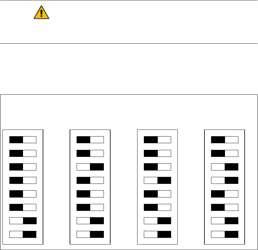
2.10.1.2 DIP Switches on the Vision Board
Legend
(1) Boot - CAN Processor 16 Bit at Sub board
(2) Reset - CAN Processor 16 Bit at Sub board
(3) P0 - Gantry address switch 1
(4) P1 - Gantry address switch 2
(5) WPE - Write protect enable at the moment OFF
(6) CANR-CANterminator
(7) Test 1 - CAN 1MBit/s ON
(8) Test 0 - CAN group ON
DIP Switch
ON
78123456
ON
78123456
ON
78123456
ON
78123456
Gantry 1
Gantry 2
not used
Gantry 3 Gantry 4
2 English Installation and Getting StartedwithCACCIA
2.10 Overview of the Jumper Settings for Individual Subsystems Issue 07/2004
42
2.10.2 SIPLACEHF3:DescriptionoftheSwitchesandPCBBoardsontheC&PHead
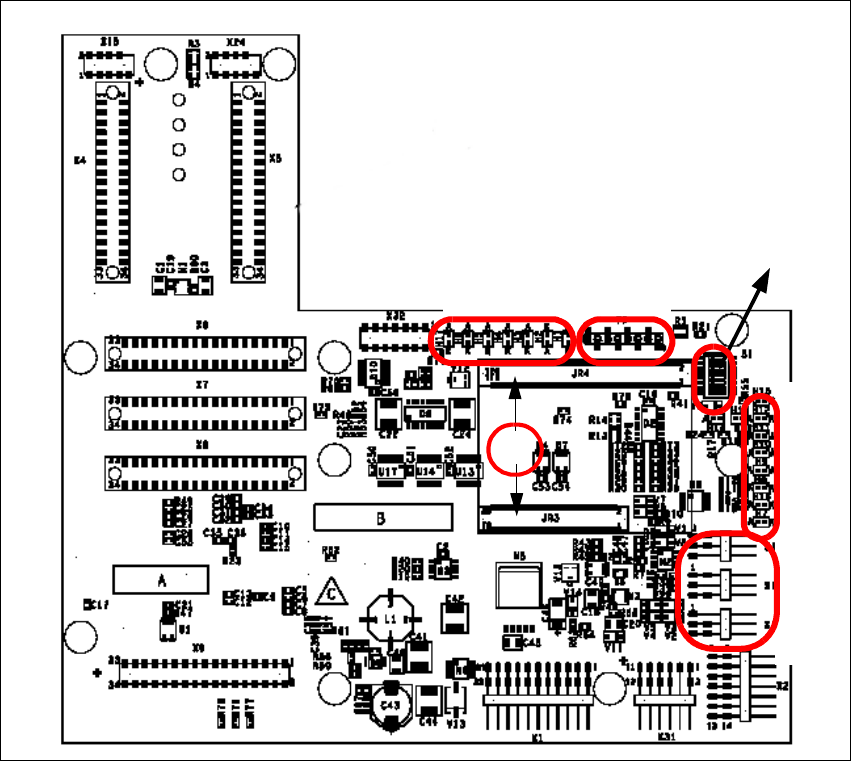
2.10.2.1 Head Interface
The same head interface board will be use on gantry 1 and gantry 2 for the Twin head and C&P
head.
Fig. 2 - 33 Head interface
Legend
(1) X11 Connector Temperature sensor X-Axis
(2) X17 Connector BERO Travel range X-Axis
(3) X16 Connector BERO Travel range X-Axis
(4) X15 Connector for incremental encoder X-Axis
(5) X24 Test connector digital track signals X-Axis
(6) Connector for "One wire" Processor board
LED 1-7 TP 1-8
LED 1-10
DIP Switch
1
2
3
4
5
6
Installation and Getting Started with CACCIA 2 English
Issue 07/2004 2.10 Overview of the Jumper Settings for Individual Subsystems
43
Description
LED‘S and DIP switches on the head interface:
LED 1-7 (functional check)
– SPI - Serial parallel interface (A/D or D/A converter in future)
– D-ON - Digital ON 5V DC/DC Converter
– H-OK - Head adapter board connected
– C-In - CAN Internal not used
– MRST - Main Reset
–F-UC- notused
– MP - Main Power fail, mean 5 V power supply being missing at the machine
(e.g. CAN Bus)
LED 1-10 (LED´s for voltages)
– Vcc - Power supply +5 V head interface
– N15V - Minus 15 Volt (from the Axis unit → Error → LED red)
– P3,3V - Not used
– P15V - Plus 15 Volt (from the Axis unit → Error → LED red)
– P24V - 24 Volt power supply (e.g. stepper motor)
–AVER-Notused
– ENAN- Notused
– P5V - 5 Volt Power supply track signals X-Axis → ON Power fail
– VccF - 5 Volt for digital
– TMP - Temperature monitoring X-Axis