00193790-01.pdf - 第115页
Installation and Getting Started with CACCIA 2 English Issue 07/2004 2.10 O verview of the J umper Settings for Individual Subsystems 49 Switch Position on the H ead Board 2 Fig. 2 - 40 T able: DI P Switches The wiring o…
2 English Installation and Getting StartedwithCACCIA
2.10 Overview of the Jumper Settings for Individual Subsystems Issue 07/2004
48
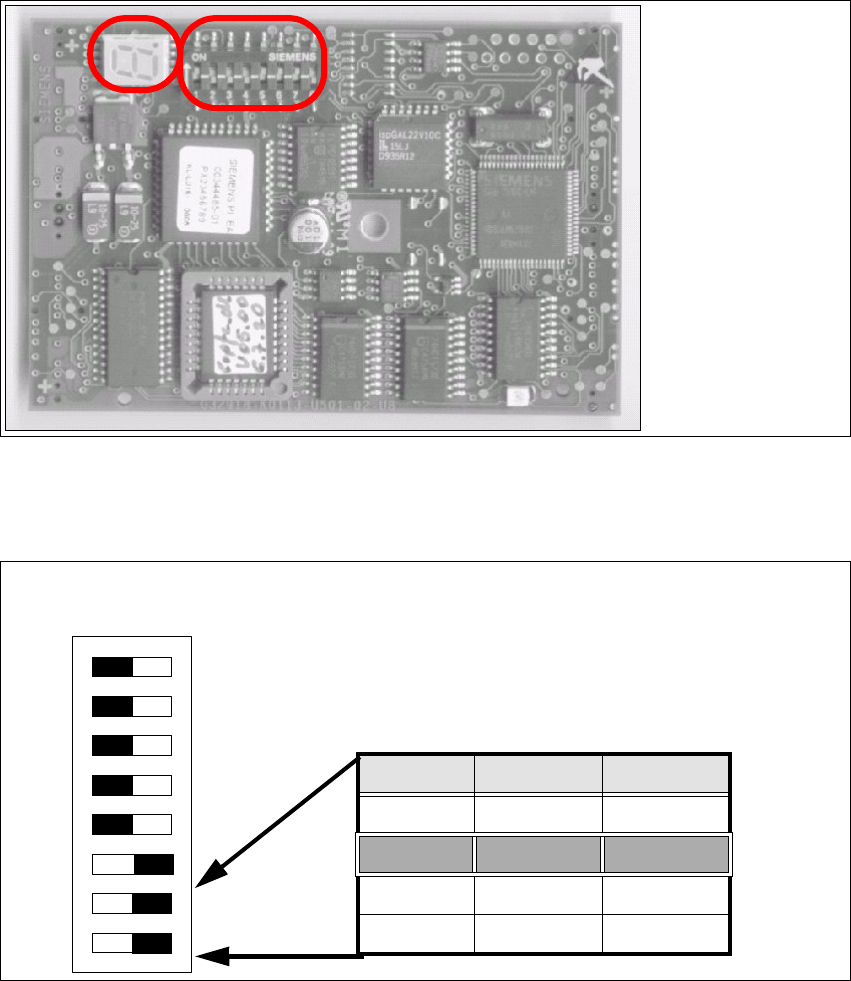
2.10.2.6 CAN Processor Board 8Bit 80C515C on the Head Adapter C&P
Fig. 2 - 38 CAN Processor board
Fig. 2 - 39 Table: DIP Switches
Description
DIP Switches and
7 Segment display
see below.
DIP Switch
ON
78123456
Gantries Switch 7 Switch 8
Gantry 1 ON ON
Gantry 2 ON OFF
Gantry 3 OFF ON
Gantry 4 OFF OFF

Installation and Getting Started with CACCIA 2 English
Issue 07/2004 2.10 Overview of the Jumper Settings for Individual Subsystems
49
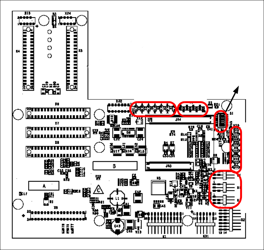
Switch Position on the Head Board
2
Fig. 2 - 40 Table: DIP Switches
The wiring of the switch depends on the placement machine involved:
Jumper 1: ON → CAN matching resistor on the placement head is set
(S-20, F4, F5), S-23, S-25 HM,F5HM.
OFF → CAN_matching resistor is not wired on the head (HS/HF default)
Jumper 2: ON → Setting during the download
OFF → Default status
Jumper 3: ON → Test mode
OFF → Default status
Jumper 4: ON → Test mode (setting of CAN ID)
OFF → Default status
Jumper 5: ON → Default status
OFF → Switch off CAN Objects component-, LP vision and IC head on the
modular Head FW (only for SIPLACE HF)
Jumper 6: ON → Default status
Jumper7,8:CAN_ID:
Standard OFF OFF OFF OFF ON ON CAN_Addresse
Switch
position
1
CAN_R120
2
EPROM_WE
3
Test _Mode
4
CAN_ERR_
SWITCH
5
Jumper 5
6
Jumper 6
7
CAN_ID1
8
CAN_ID0
ON X
see
above
see above
OFF X X X X X
see
above
see above
2 English Installation and Getting StartedwithCACCIA
2.10 Overview of the Jumper Settings for Individual Subsystems Issue 07/2004
50
2.10.3 SIPLACE HF3: Switches and PCB Boards on the Twin Head:
2.10.3.1 Head Interface
The same head interface board is used on gantry 1/2 for the Twin head and C&P head.
Fig. 2 - 41 Head Interface
Legend
(1) X11 Connector Temperature sensor X-Axis
(2) X17 Connector BERO travel range X-Axis
(3) X16 Connector BERO travel range X-Axis
(4) X15 Connector for incremental encoder X-Axis
(5) X24 Test connector digital track signals X-Axis
LED 1-7 TP 1-8
LED 1-10
DIP Switch
1
2
3
4
5