00193790-01.pdf - 第122页
2 English Installat ion and Getting Started with CACCIA 2.10 Overview of the J umper Settings for Individual Subsyst ems Issue 07/2004 56 Legend (1) Conn ector for the 16 Bi t CAN Bus Pr ocessor (C ontrol the a nalog or …
Installation and Getting Started with CACCIA 2 English
Issue 07/2004 2.10 Overview of the Jumper Settings for Individual Subsystems
55
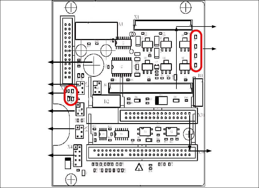
2.10.3.5 Twin Head Main Board
The main board is mounted directly on the top of the frame of the Twin head. This board is
connected to the head adapter via ribbon cable (one ribbon cable for each axis).
Fig. 2 - 45 Main board Twin head
1
2
3
4
6
5
7
8
9
2 English Installation and Getting StartedwithCACCIA
2.10 Overview of the Jumper Settings for Individual Subsystems Issue 07/2004
56
Legend
(1) Connector for the 16BitCAN Bus Processor (Control the analog or digitalvacuum generator)
(2) LED´S (Description from top to bottom)
-D6BEROZ-axis top (not used)
- D1 not defined
-D2ClampingZ-axis (yellow) LED off, retract unit is at top position.
- D15 Temperature monitoring Z-axis linear motor (red) LED on, is ok.
(3) Connectors to the head adapter
(4) Connector track signals Z-axis
(5) Connector BERO Z-axis (not used)
(6) Connector pneumatic valve (retract unit)
(7) LED‘s: D7 - is ON after reference run
D8 - protect Z-axis without function
D9 - without function
D10 - green LED ON 24Vfor the vacuum generator
D14 - Alarm output for the vacuum generator (red LED ON vacuum generator defect)
(8) Connector for valve (only 24 Volts on pin 2 and 4 measured)
(9) Hole for pneumatic pipe to the vacuum generator
Installation and Getting Started with CACCIA 2 English
Issue 07/2004 2.10 Overview of the Jumper Settings for Individual Subsystems
57
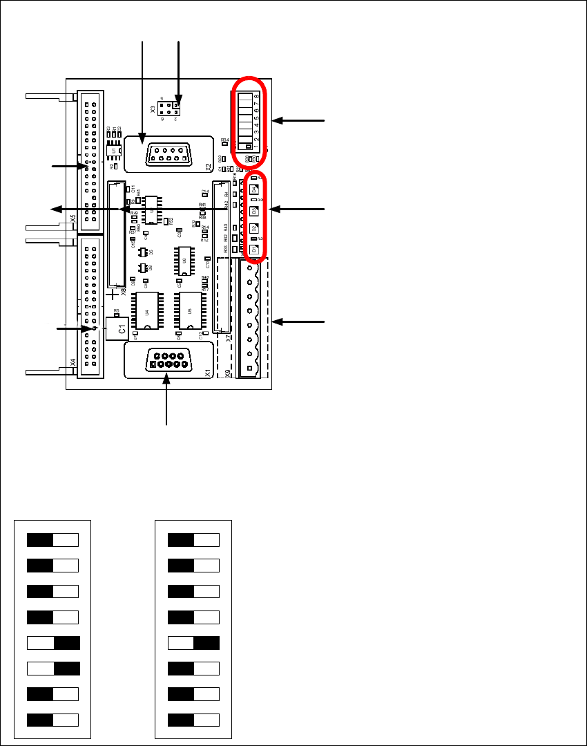
2.10.3.6 Vision Control Board "IC camera"
The vision control board is installed in sector 2 for the Twin head on gantry 3 and at sector 4 for
the Twin head on gantry 1 (only for SIPLACE HF).
Fig. 2 - 46 Vision control board IC camera
1
6
3
4
5
2
7
8
9
to 5)DIP Switch
(1) CAN Terminator
(2) RESET
(3) Bootstrap
(4) TEST
(5) P1 Address Switch
(6) P0 Address Switch
(7) CAN - ID 1
(8) CAN - ID 0
DIP Switch
ON
78123456
ON
78123456
Gantry 1
for HF
Gantry 2
for HF/HF3