00193790-01.pdf - 第120页
2 English Installat ion and Getting Started with CACCIA 2.10 Overview of the J umper Settings for Individual Subsyst ems Issue 07/2004 54 2.10.3.4 Head Adapter T w in He ad The hea d ada pter board connects the h ead int…
Installation and Getting Started with CACCIA 2 English
Issue 07/2004 2.10 Overview of the Jumper Settings for Individual Subsystems
53
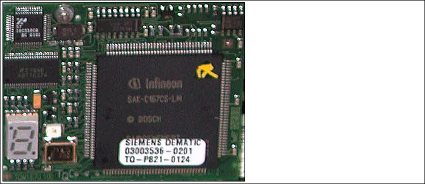
2.10.3.3 CAN Processor Board 16 Bit
The 16 Bit CAN Processor is used for different functions of the following units:
– Vision board, communication and control via the ICOS system
– Main board Twin head, control the vacuum generator
– Vision board for the stationary IC (FC) camera, communication and control via the ICOS
system
Fig. 2 - 43 16 Bit Processor
Description 7 Segment display (Standard mode "." flashed):
– After switch ON the machine "0" appears on the display
– Display "b" Bios is started.
– Display flash alternately "b" and "." → none Application available or can not started.
– Display "-I" und "I-" Application is loaded and now starts.
– The "." on the display flashed.
(1) 7 Segment display
(2) LED red at the manual RESET on
the Processors
(3) 16 Bit Processor
2
3
1
2 English Installation and Getting StartedwithCACCIA
2.10 Overview of the Jumper Settings for Individual Subsystems Issue 07/2004
54
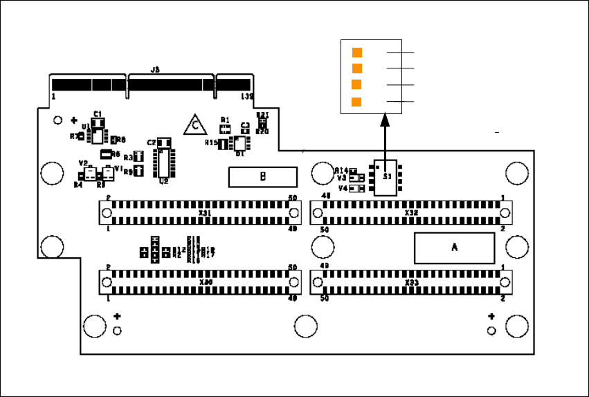
2.10.3.4 Head Adapter Twin Head
Theheadadapter board connects theheadinterface board directly to the mainboardof Twinhead
segment 1 and 2 via ribbon cable. This head adapter must be changed for head modularity, if you
use a C&P head.
Fig. 2 - 44 Head adapter Twin head
Legend
(1) Connector Z-Axis Twin head 1
(2) Connector D-Axis Twin head 1
(3) Connector DP-Axis Twin head 2
(4) Connector Z-Axis Twin head 2
(5) PP1 Boot CAN Processor Twin Segm. 1
(6) PP1 Reset CAN Processor Twin Segm. 1
(7) PP2 Boot CAN Processor Twin Segm. 2
(8) PP2 Reset CAN Processor Twin Segm. 2
1
24
3
OFF
1
4
5
6
7
8
Installation and Getting Started with CACCIA 2 English
Issue 07/2004 2.10 Overview of the Jumper Settings for Individual Subsystems
55
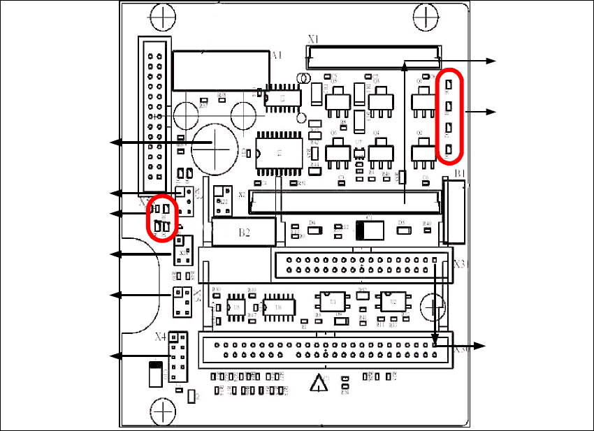
2.10.3.5 Twin Head Main Board
The main board is mounted directly on the top of the frame of the Twin head. This board is
connected to the head adapter via ribbon cable (one ribbon cable for each axis).
Fig. 2 - 45 Main board Twin head
1
2
3
4
6
5
7
8
9