00193790-01.pdf - 第123页
Installation and Getting Started with CACCIA 2 English Issue 07/2004 2.10 O verview of the J umper Settings for Individual Subsystems 57 2.10.3.6 V ision Control Board "IC camera" The vi sion contr ol board is …
2 English Installation and Getting StartedwithCACCIA
2.10 Overview of the Jumper Settings for Individual Subsystems Issue 07/2004
56
Legend
(1) Connector for the 16BitCAN Bus Processor (Control the analog or digitalvacuum generator)
(2) LED´S (Description from top to bottom)
-D6BEROZ-axis top (not used)
- D1 not defined
-D2ClampingZ-axis (yellow) LED off, retract unit is at top position.
- D15 Temperature monitoring Z-axis linear motor (red) LED on, is ok.
(3) Connectors to the head adapter
(4) Connector track signals Z-axis
(5) Connector BERO Z-axis (not used)
(6) Connector pneumatic valve (retract unit)
(7) LED‘s: D7 - is ON after reference run
D8 - protect Z-axis without function
D9 - without function
D10 - green LED ON 24Vfor the vacuum generator
D14 - Alarm output for the vacuum generator (red LED ON vacuum generator defect)
(8) Connector for valve (only 24 Volts on pin 2 and 4 measured)
(9) Hole for pneumatic pipe to the vacuum generator
Installation and Getting Started with CACCIA 2 English
Issue 07/2004 2.10 Overview of the Jumper Settings for Individual Subsystems
57
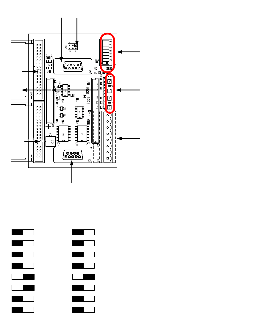
2.10.3.6 Vision Control Board "IC camera"
The vision control board is installed in sector 2 for the Twin head on gantry 3 and at sector 4 for
the Twin head on gantry 1 (only for SIPLACE HF).
Fig. 2 - 46 Vision control board IC camera
1
6
3
4
5
2
7
8
9
to 5)DIP Switch
(1) CAN Terminator
(2) RESET
(3) Bootstrap
(4) TEST
(5) P1 Address Switch
(6) P0 Address Switch
(7) CAN - ID 1
(8) CAN - ID 0
DIP Switch
ON
78123456
ON
78123456
Gantry 1
for HF
Gantry 2
for HF/HF3
2 English Installation and Getting StartedwithCACCIA
2.10 Overview of the Jumper Settings for Individual Subsystems Issue 07/2004
58
Legend
(1) Connector for FC camera illumination
(2) Connector for IC camera illumination
(3) Service connector
(4) LED‘s (downwards D4 - D1)
– + 5V/-15V/+15 V / +40 V
(5) DIP Switch
(6) Connector CAN Bus
(7) Power supply vision control board
Connector for DC/DC converter (Section2)
for DC/DC distributor (section 4)
(8) Connectors for CAN Bus Processor 16 Bit
(9) Flash signal