00195044-10_UM_VisionTeachStation_DE EN.pdf - 第133页
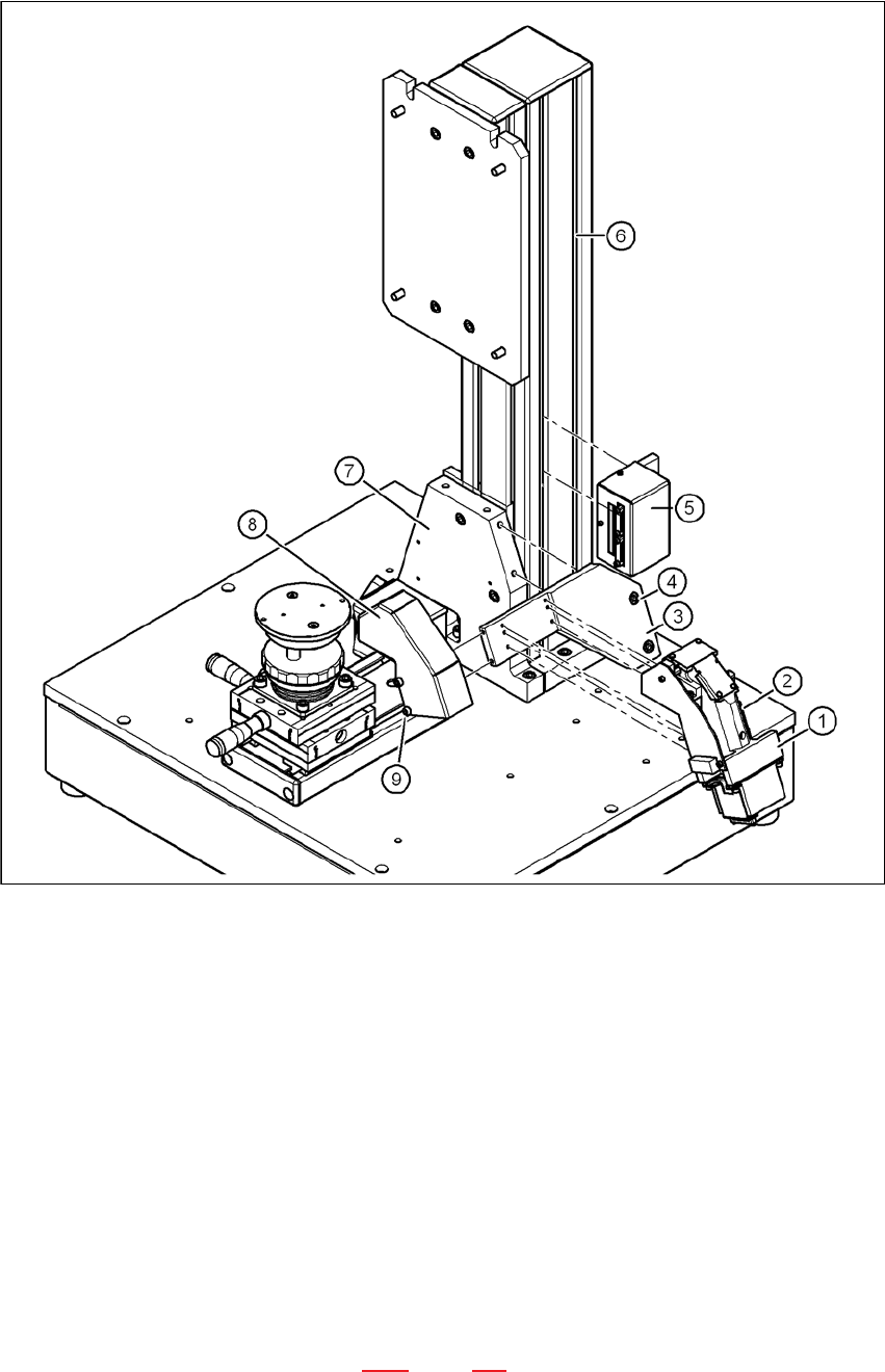
Vision Teach Station User Manual 5 Installing the cameras 12/2012 Edition 5.3 Installing the type 23 head camera 133 5.3.4 Fitting the component support 5 Fig. 5.3 - 12 Base module with camera type 23 (1) Magnetic switch…
5 Installing the cameras Vision Teach Station User Manual
5.3 Installing the type 23 head camera 12/2012 Edition
132
5
Fig. 5.3 - 11 Installing camera type 23
(1) Camera type 23
(2) Hexagon socket head screw M3 x 12, 4x
(3) Mount for camera type 23
(4) Hexagon socket head screw M6 x 12, 2x
(5) Adapter for head camera
(6) Pillar
(7) "Bottom" mounting plate"
(8) Cover for camera type 23
(9) Hexagon socket head screw M4 x 8, 2x
5.3.3 Running the cables
Run the cables as described in section 5.2.3, page 127.
Vision Teach Station User Manual 5 Installing the cameras
12/2012 Edition 5.3 Installing the type 23 head camera
133
5.3.4 Fitting the component support
5
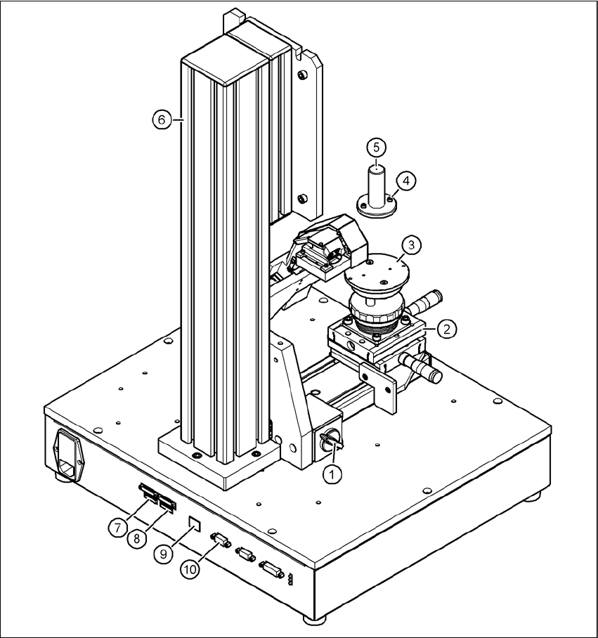
Fig. 5.3 - 12 Base module with camera type 23
(1) Magnetic switch
(2) Positioning unit
(3) Holder for component support
(4) Hexagon socket head screw M3 x 10, 2x
(5) Component support, camera type 23
(6) Pillar
(7) Connection for cable, head camera 1 (03040353-W1: 26-pin, 03040353-W2: 12-pin)

5 Installing the cameras Vision Teach Station User Manual
5.3 Installing the type 23 head camera 12/2012 Edition
134
(8) Connection for cable, head camera 2 (03040353-W1: 26-pin, 03040353-W2: 12-pin)
(9) Connection for camera bus cable to the PC (03040359-xx)
(10)Connection for CAN bus cable to the PC (03040362-xx)
Release the lock on the positioning unit (item 2 in Fig. 5.3 - 12, page 133) using the magnetic
switch (item 1 in Fig. 5.3 - 12, page 133)
Push the positioning unit out.
Fix the component support (item 5 in Fig. 5.3 - 12, page 133) using the two hexagon socket
head screws M3 x 10 (item 4 in Fig. 5.3 - 12, page 133) to the holder (item 3 in Fig.
5.3 - 12, page 133).
Push the positioning unit (item 2 in Fig. 5.3 - 12, page 133) back towards the pillar (item 6 in
Fig. 5.3 - 12, page 133) and lock the positioning unit in place.
WARNING 5
Always make sure that the base module and PC are switched off when you connect or re-
move connectors.
NEVER unplug the 26-pin ribbon cable while it is carrying voltage as this could damage the
LED driver board for the camera. 5
5.3.5 Connecting the adapter, base module and PC
Run the cables as described in section 5.2.5, page 130.