00195044-10_UM_VisionTeachStation_DE EN.pdf - 第179页
Vision Teach Station User Manual 11 Measuring components 12/2012 Edition 11.2 Measuring the component 179 Tab. 11.2 - 1 Programming steps with the vision teach station Alternatively, all the programming can be prepared i…
11 Measuring components Vision Teach Station User Manual
11.2 Measuring the component 12/2012 Edition
178
11.2.2 Programming steps with the vision teach station
The following table guides you through the individual steps for programming a package form.
We distinguish between three programming areas:
– The two areas of the SIPLACE Vision Teach Station software
accessed via the Start SIPLACE Pro and Measurement buttons.
– The SIPLACE Pro Desk programming interface
Programming area Action Detail / Special feature
SIPLACE vision teach
station button:
SIPLACE Pro
Selects the PF directory and the
prepared PACKAGE FORM.
Or recreate a PACKAGE FORM by right-
clicking in the free area.
Enter the required PF name in the dialog.
Enter the body dimension Z with
tolerance
(data sheet/ caliper gauge).
X/Y PF dimensions are changed at the vision
teach station.
Button: Geometry.
Enter comment about the package
form.
Can also be entered before programming in
SIPLACE Vision.
SIPLACE vision teach
station button:
Start measurement
Add the PF under the camera
(see section
11.1, page 173).
Move X/Y cross-bed with component in be-
neath the camera. Adjust the height with the
"focus gauge".
Switch on magnet and modify the X-Y positi-
on of the cross-bed so that the component
appears in the middle beneath the camera.
Start measurement
The camera image and the SIPLACE Vision
menus are displayed.
Select the Geometry button.
Select the appropriate package form type and
program the body dimensions.
Program connection geometry
Program the lead or ball/pillar geometry or the
corner/polygon circle for the groups concer-
ned.
All contacts recorded?
Program the connections and repeat until all
the connection groups are recorded.
Pay particular attention to the tole-
rances (defaults when program-
ming) of the programmed set-
points.
Tolerances:
up to 30% is recommended in all package
form geometries;
over 40% (pin width) - the measuring algo-
rithms can be affected;
over 50% - not permitted.
Vision Teach Station User Manual 11 Measuring components
12/2012 Edition 11.2 Measuring the component
179
Tab. 11.2 - 1 Programming steps with the vision teach station
Alternatively, all the programming can be prepared in SIPLACE Pro and then tested at the
SIPLACE vision teach station.
SIPLACE vision teach
station button:
Start measurement
Test PACKAGE FORM:
The optical centering should provide a stable
result. Tested with several components at
various angles.
Measurement failed? No: Save
Yes: Correct the geometry
or modify the illumination.
Measurement failed? No: Save
Yes: It may also be necessary to
modify the algorithm.
This is only necessary in exceptional circum-
stances.
PACKAGE FORM tested success-
fully (multiple times)?
No: Repeat previous menu
Yes: Save PACKAGE FORM
by switching to the SIPLACE Pro
menu.
SIPLACE Pro Desk
Programming of the
handling data; check with station
configuration
Assignment of nozzles; camera; reduced ac-
celeration of the axes; processing data; fee-
der type
Export PACKAGE FORM and
save to a memory stick.
Export data model
Import the PACKAGE FORM on
the SIPLACE Pro computer on the
line.
Import data model
Programming area Action Detail / Special feature
12 Coordinate systems of the component cameras Vision Teach Station User Manual
11.2 Measuring the component 12/2012 Edition
180
12 Coordinate systems of the component cameras
Representation of the preferred 0° position on the SIPLACE Pro computer and on the vision
teach station 12
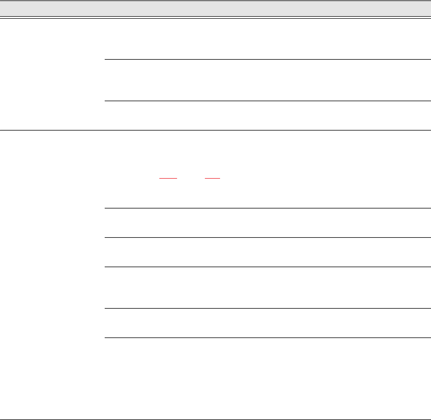
The following illustrations show how the package form is represented in the preferred 0° position
on the SIPLACE Pro computer or on the SIPLACE vision teach station.
12
Fig. 12.0 - 1 Representation of the preferred 0° position on the SIPLACE Pro computer and on the vision teach station
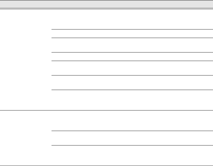
Alignment of the components in the preferred 0° position 12
12
Fig. 12.0 - 2 Alignment of the components in the preferred 0° position - SST 23
SIPLACE Pro computer
SIPLACE Vision Teach Station
SST23
0° component position
on the component camera
of the C&P20 head