00195044-10_UM_VisionTeachStation_DE EN.pdf - 第175页
Vision Teach Station User Manual 11 Measuring components 12/2012 Edition 11.1 Preparing components for the measurement 175 11 Fig. 11.1 - 1 Base module - Placing the component on the component support (1) Magnetic switch…

11 Measuring components Vision Teach Station User Manual
11.1 Preparing components for the measurement 12/2012 Edition
174
PLEASE NOTE: 11
It is very important to accurately set the distance between the component and the camera,
otherwise the component cannot be mapped correctly on the camera, i.e. the shape of the
image will not correspond exactly to the shape of the component. If the distance is wrong, the
component will appear too large or too small. The geometric description will not tally with the
actual component. 11
Vision Teach Station User Manual 11 Measuring components
12/2012 Edition 11.1 Preparing components for the measurement
175
11
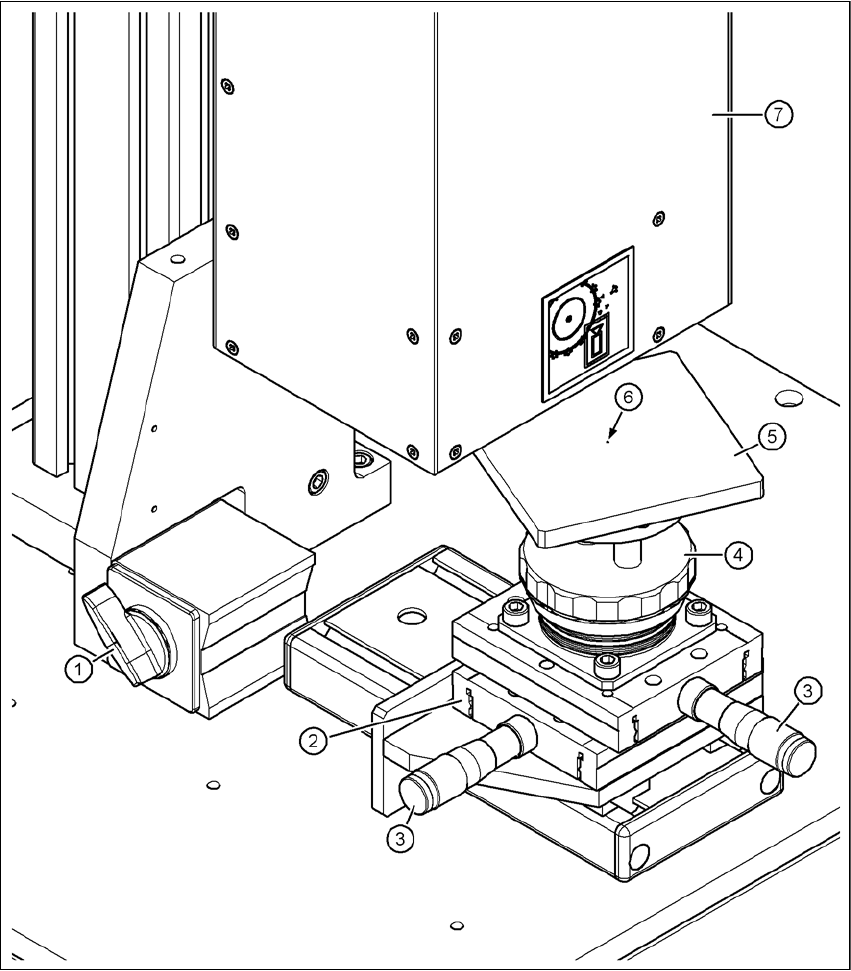
Fig. 11.1 - 1 Base module - Placing the component on the component support
(1) Magnetic switch
(2) Positioning unit
(3) Micrometer screw for positioning the component support
(4) Adjusting ring for adjusting the height of the component support
(5) Component support, rotating, for optimum angular alignment during the measurement
(6) Centering fiducial on the component support
(7) Component camera
11 Measuring components Vision Teach Station User Manual
11.1 Preparing components for the measurement 12/2012 Edition
176
Push the positioning unit (item 2 in Fig. 11.1 - 1, page 175) until the end stop is under the
camera.
Lock the positioning unit (item 2 in Fig. 11.1 - 1, page 175) using the magnetic switch (item 1
in Fig. 11.1 - 1, page 175)
Check the camera image on the monitor and position the middle of the component at the
camera center point using the micrometer screw (item 3 in Fig. 11.1 - 1, page 175).
If necessary, turn the component so that the outer edges run parallel to the edge of the image.
11
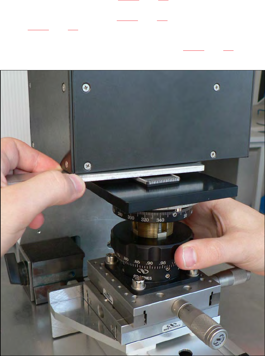
Fig. 11.1 - 2 Setting the focus point with the adjustment guide