2500_Users_Manual-.pdf - 第192页
PRESS NUMBER OF SOLENOID, E TO EXIT 1 - UNUSED 4 - BEAM UP 7 - VACUUM 2 - BLOWER 5 - BLOWER OFF 8 - CLAMP 3 - CUT OFF 6 - HIGH PRESSURE 1949-2 SOLENOIDS (2, 3) MAIN PLATE (under side) PROGRAMMING ELECTRONICS ASSEMBLY SOL…
2303-1
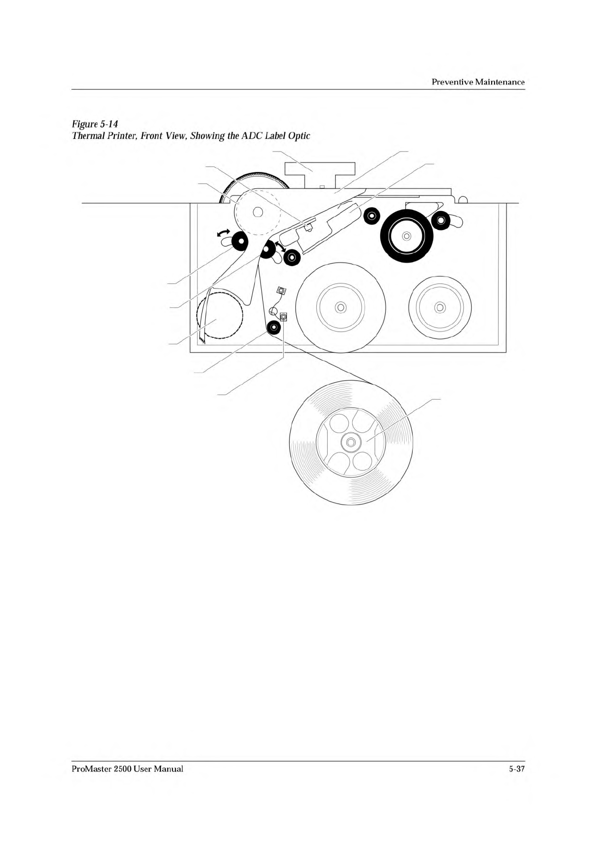
LABEL DRIVE ROLLER (hidden)
LABEL PINCH ROLLER
LABEL ADVANCE KNOB
LABEL ALIGNMENT ROLLER
LABEL DETECTION OPTIC
LABEL ROLL
(cover removed)
APPLICATION PLATE (raised)
PLATEN
PRINT HEAD
(retracted position)
LABEL ADC OPTIC
PLATEN PINCH ROLLER
Preventive
Maintenance
Figure
5-14
Thermal
Printer,
Front
View,
Showing
the
ADC
Label
Optic
ProMaster
2500
User
Manual
5-37
PRESS NUMBER OF SOLENOID, E TO EXIT
1 - UNUSED 4 - BEAM UP 7 - VACUUM
2 - BLOWER 5 - BLOWER OFF 8 - CLAMP
3 - CUT OFF 6 - HIGH PRESSURE
1949-2
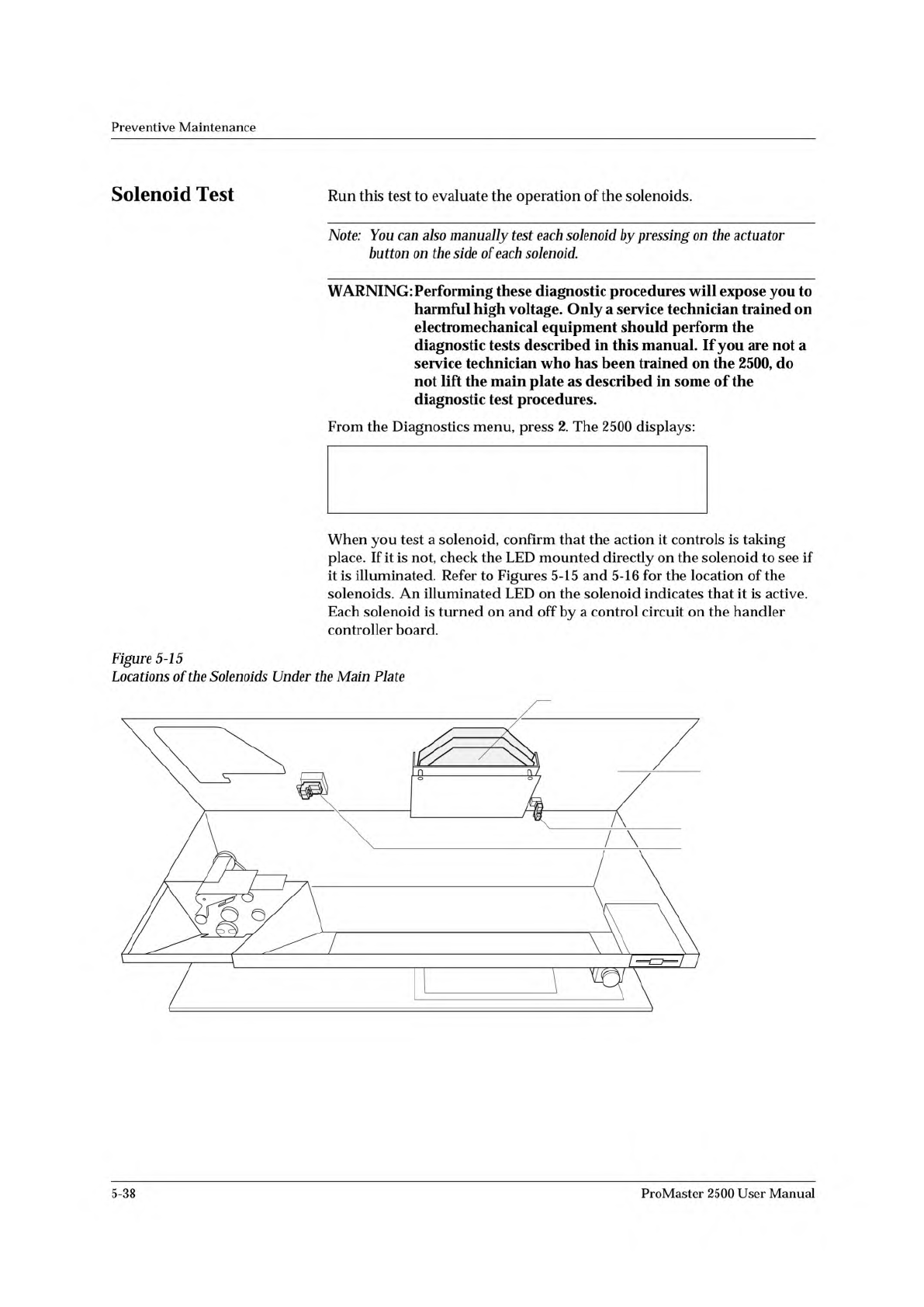
SOLENOIDS (2, 3)
MAIN PLATE
(under side)
PROGRAMMING ELECTRONICS ASSEMBLY
SOLENOID (8)
Preventive
Maintenance
Solenoid
Test
Run
this
test
to
evaluate
the
operation
of
the
solenoids.
Note:
You
can
also
manually
test
each
solenoid
by
pressing
on
the
actuator
button
on
the
side
of
each
solenoid.
WARNING:
Performing
these
diagnostic
procedures
will
expose
you
to
harmful
high
voltage.
Only
a
service
technician
trained
on
electromechanical
equipment
should
perform
the
diagnostic
tests
described
in
this
manual.
If
you
are
not
a
service
technician
who
has
been
trained
on
the
2500,
do
not
lift
the
main
plate
as
described
in
some
of
the
diagnostic
test
procedures.
From
the
Diagnostics
menu,
press
2.
The
2500
displays:
When
you
test
a
solenoid,
confirm
that
the
action
it
controls
is
taking
place.
If
it
is
not,
check
the
LED
mounted
directly
on
the
solenoid
to
see
if
it
is
illuminated.
Refer
to
Figures
5-15
and
5-16
for
the
location
of
the
solenoids.
An
illuminated
LED
on
the
solenoid
indicates
that
it
is
active.
Each
solenoid
is
turned
on
and
off
by
a
control
circuit
on
the
handler
controller
board.
Figure
5-15
Locations
of
the
Solenoids
Under
the
Main
Plate
5-38
ProMaster
2500
User
Manual
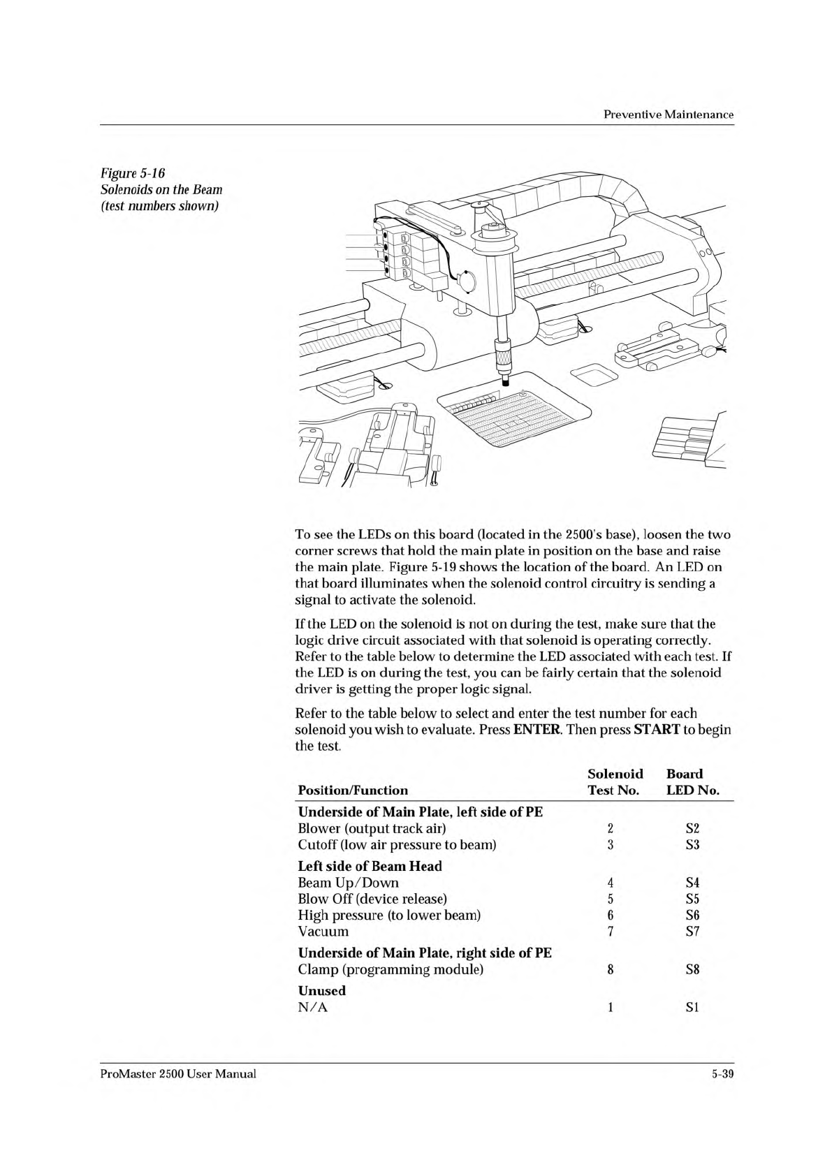
1940-1
7
6
5
4
Preventive
Maintenance
Figure
5-16
Solenoids
on
the
Beam
(test
numbers
shown)
To
see
the
LEDs
on
this
board
(located
in
the
2500's
base),
loosen
the
two
corner
screws
that
hold
the
main
plate
in
position
on
the
base
and
raise
the
main
plate.
Figure
5-19
shows
the
location
of
the
board.
An
LED
on
that
board
illuminates
when
the
solenoid
control
circuitry
is
sending
a
signal
to
activate
the
solenoid.
If
the
LED
on
the
solenoid
is
not
on
during
the
test,
make
sure
that
the
logic
drive
circuit
associated
with
that
solenoid
is
operating
correctly.
Refer
to
the
table
below
to
determine
the
LED
associated
with
each
test.
If
the
LED
is
on
during
the
test,
you
can
be
fairly
certain
that
the
solenoid
driver
is
getting
the
proper
logic
signal.
Refer
to
the
table
below
to
select
and
enter
the
test
number
for
each
solenoid
you
wish
to
evaluate.
Press
ENTER.
Then
press
START
to
begin
the
test.
Solenoid
Board
Position/Function
Test
No.
LED
No.
Underside
of
Main
Plate,
left
side
of
PE
Blower
(output
track
air)
2
S2
Cutoff
(low
air
pressure
to
beam)
3
S3
Left
side
of
Beam
Head
Beam
Up/Down
4
S4
Blow
Off
(device
release)
5
S5
High
pressure
(to
lower
beam)
6
S6
Vacuum
7
S7
Underside
of
Main
Plate,
right
side
of
PE
Clamp
(programming
module)
8
S8
Unused
N/A
1
SI
ProMaster
2500
User
Manual
5-39