2500_Users_Manual-.pdf - 第227页
Ω Ω 2074-2 MAIN PLATE MAIN PLATE SCREW (1 of 2) HOOD MAIN PLATE SCREW (2 of 2) Repair and Replacement Procedures 5. Insert the fuse holder into its slot with the arrow pointing in the same direction as the arrows on the …
1242-1
1243-1
SPARE FUSE FUSE HOLDER
Repair
and
Replacement
Procedures
Fuse
Replacement
The
main
fuse
is
located
behind
the
power
cord
input
assembly.
Perform
the
following
procedure
to
replace
the
main
fuse.
CAUTION:
For
continued
protection
against
the
possibility
of
fire,
replace
the
blown
fuse
only
with
a
fuse
of
the
same
voltage,
current,
and
type.
1.
Turn
off
the
2500
and
remove
the
power
cord.
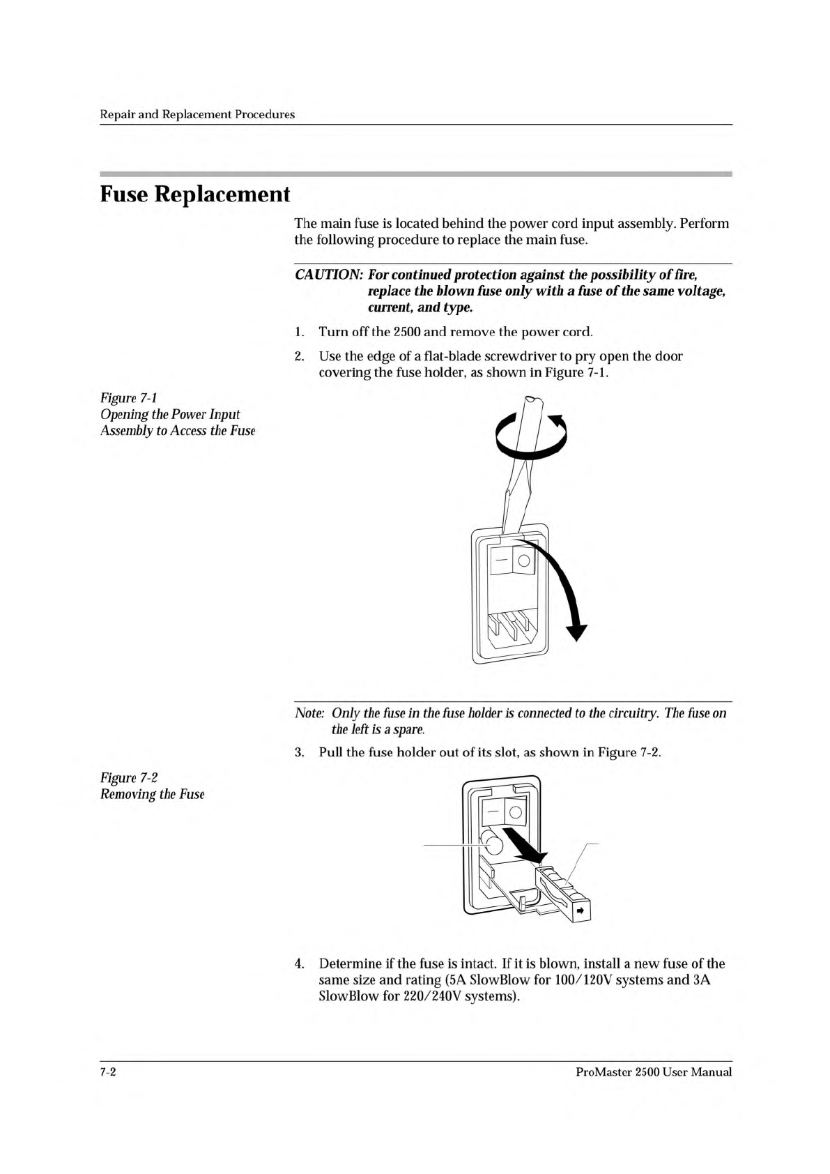
2.
Use
the
edge
of
a
flat-blade
screwdriver
to
pry
open
the
door
covering
the
fuse
holder,
as
shown
in
Figure
7-1.
Figure
7-1
Opening
the
Power
Input
Assembly
to
Access
the
Fuse
Note:
Only
the
fuse
in
the
fuse
holder
is
connected
to
the
circuitry.
The
fuse
on
the
left
is
a
spare.
3.
Pull
the
fuse
holder
out
of
its
slot,
as
shown
in
Figure
7-2.
Figure
7-2
Removing
the
Fuse
4.
Determine
if
the
fuse
is
intact.
If
it
is
blown,
install
a
new
fuse
of
the
same
size
and
rating
(5
A
SlowBlow
for
100/120V
systems
and
3A
SlowBlow
for
220/240V
systems).
7-2
ProMaster
2500
User
Manual
Ω Ω
2074-2
MAIN PLATE
MAIN PLATE
SCREW (1 of 2)
HOOD
MAIN PLATE
SCREW
(2 of 2)
Repair
and
Replacement
Procedures
5.
Insert
the
fuse
holder
into
its
slot
with
the
arrow
pointing
in
the
same
direction
as
the
arrows
on
the
door
and
snap
the
door
closed.
Programming
Electronics
Assembly
Replacement
Removing
the
PE
Follow
the
steps
below
to
remove
the
PE
assembly
from
the
2500.
The
PE
assembly
is
mounted
on
the
underside
of
the
2500's
main
plate.
You
will
need
to
raise
the
main
plate
and
use
a
7/64-inch
hex
wrench
to
complete
the
removal
procedure.
WARNING:
This
procedure
should
be
performed
by
a
service
technician
trained
on
electromechanical
equipment.
Do
not
attempt
this
procedure
unless
you
are
qualified
to
do
so.
Dangerous
high
voltages
are
generated
under
the
main
plate
that
could
cause
a
harmful
electrical
shock.
Turn
off
the
2500
before
you
begin
this
procedure.
To
help
eliminate
damage
from
ESD,
wear
an
antistatic
wrist
strap
that
contains
a
IM
(minimum)
to
10M
(maximum)
isolating
resistor.
The
wrist
strap
should
be
connected
to
the
grounding
plug.
1.
Turn
off
the
2500
and
remove
the
power
cord.
2.
Remove
the
programming
module,
if
one
is
installed.
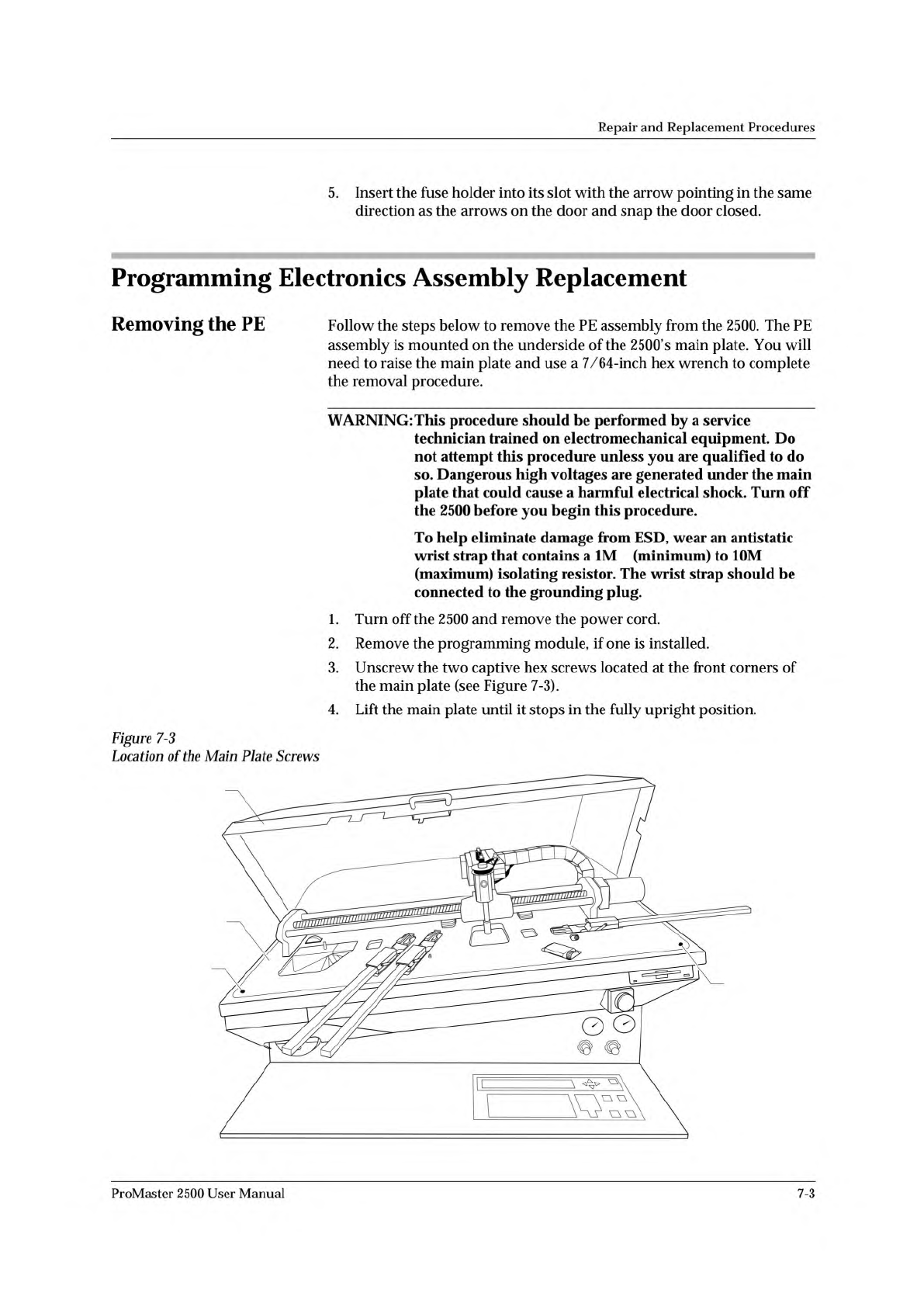
3.
Unscrew
the
two
captive
hex
screws
located
at
the
front
corners
of
the
main
plate
(see
Figure
7-3).
4.
Lift
the
main
plate
until
it
stops
in
the
fully
upright
position.
Figure
7-3
Location
of
the
Main
Plate
Screws
ProMaster
2500
User
Manual
7-3

Repair
and
Replacement
Procedures
5.
Disconnect
the
red
and
black
power
cable
from
the
connector
on
the
left
side
of
the
controller
/waveform
board.
(Figure
7-4
shows
the
location
and
polarity
of
this
cable.)
7-4
ProMaster
2500
User
Manual