L-9517-9563-06-A_Data_sheet_ATOM_en.pdf - 第15页
15 A TOM miniature encoder system 14.5 25 4.5 × 45° 2 6 5 25 9.5 4 4.6 5.6 5.6 15.75 17 2 mounting holes M3 through CAL pad CAL pad 2 mounting pillars JST output connector † 6.25 Cable input connector Pin1 Component area…
14 ATOM miniature encoder system
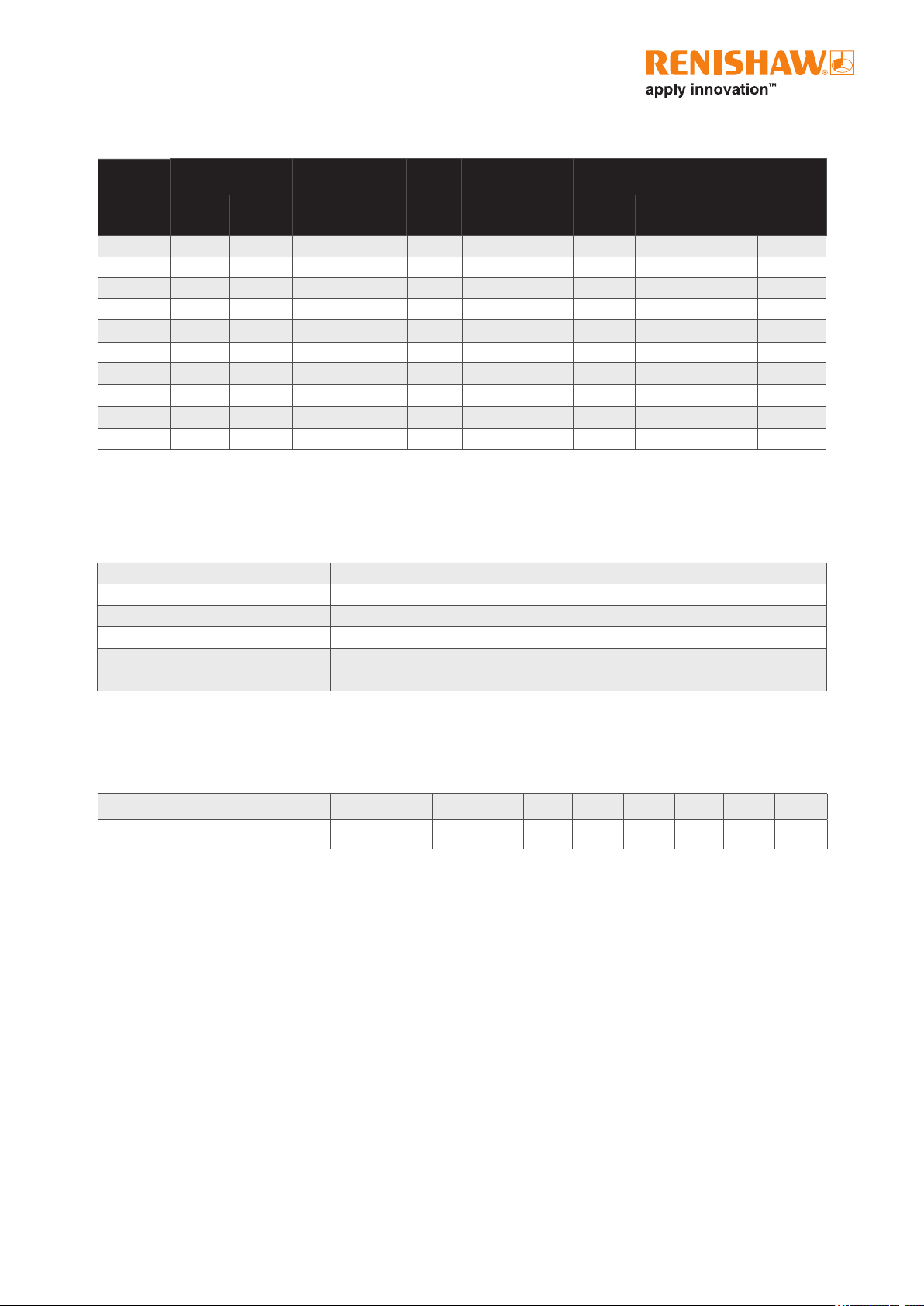
RCDM technical specications
Material Soda-lime glass
Form 2.3mm thick
Reference mark Single reference mark
Coefcient of thermal expansion ~8µm/m/°C
Nominal outer diameter (mm) 40μm 17, 20, 25, 27, 30 ,36, 50, 56, 68, 108
20μm 30, 36, 50, 56, 68, 108
Disc size (mm) 17 20 25 27 30 36 50 56 68 108
Graduation accuracy (arc seconds) 15.81 12.95 9.82 9 7.91 6.49 4.5 3.95 3.24 2.78
1
Special disc sizes available on request.
Disc size
1
(mm)
Line count
D1
(mm)
D2
(mm)
D3
(mm)
Optical
diameter
(mm)
A
(mm)
Radial tolerance
E(mm)
Longitudinal
tolerance F (mm)
20 µm
version
40 µm
version
20 µm
version
40 µm
version
20 µm
version
40 µm
version
17 - 1 024 3.275 8.1 16.9 13.04 10.63 - 0.1 - 0.1
20 - 1 250 3.275 11 19.9 15.92 12.07 - 0.1 - 0.1
25 - 1 650 6.46 16.1 24.9 21.01 14.62 - 0.125 - 0.075
27 - 1 800 9.625 18 26.9 22.92 15.57 - 0.125 - 0.075
30 4 096 2 048 12.8 21.15 29.9 26.08 17.15 0.1 0.125 0.075 0.125
36 5 000 2 500 12.8 26.9 35.9 31.83 20.03 0.125 0.175 0.075 0.2
50 7 200 3 600 25.5 40.9 49.9 45.84 27.03 0.125 0.2 0.075 0.2
56 8 192 4 096 25.5 47.25 55.9 52.15 30.19 0.125 0.2 0.1 0.2
68 10 000 5 000 25.5 58.55 67.9 63.66 35.94 0.15 0.2 0.125 0.3
108 16 384 8 192 50.9 99.2 107.9 104.3 56.26 0.2 0.2 0.225 0.3
Graduation accuracy
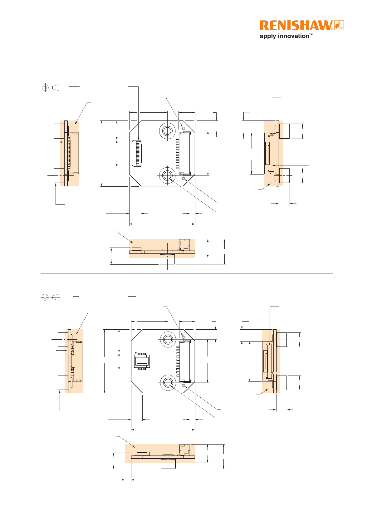
Dimensions
15 ATOM miniature encoder system
14.5
25
4.5 × 45° 2
6
5
25
9.5
4
4.6
5.6
5.6
15.75
17
2 mounting holes
M3 through
CAL pad
CAL pad
2 mounting
pillars
JST output connector
†
6.25
Cable input connector
Pin1
Component area
Component area
Component area
10
2.5
7.7
Dimensions and tolerances in mm
Cable variant dimension drawing
†
10 way JST, GH crimp connector.
1.25mm pitch.
Suitable for cable size 26 to 30 AWG.
*
10 way JST, GH crimp connector.
1.25mm pitch.
Suitable for cable size 26 to 30 AWG.
Dimensions and tolerances in mm
ACi interface
FPC variant dimension drawing
14.5
25
4.5 × 45°
2
6
10
25
7.7
9.5
4
4.6
5.6
5.6
15.75
12.5
17
2 mounting holes
M3 through
CAL pad
CAL
pad
2 mounting
pillars
JST output connector
*
6.25
Pin1
Pin1
Component area
Component area
Component area
FPC input connector
4
4
16 ATOM miniature encoder system
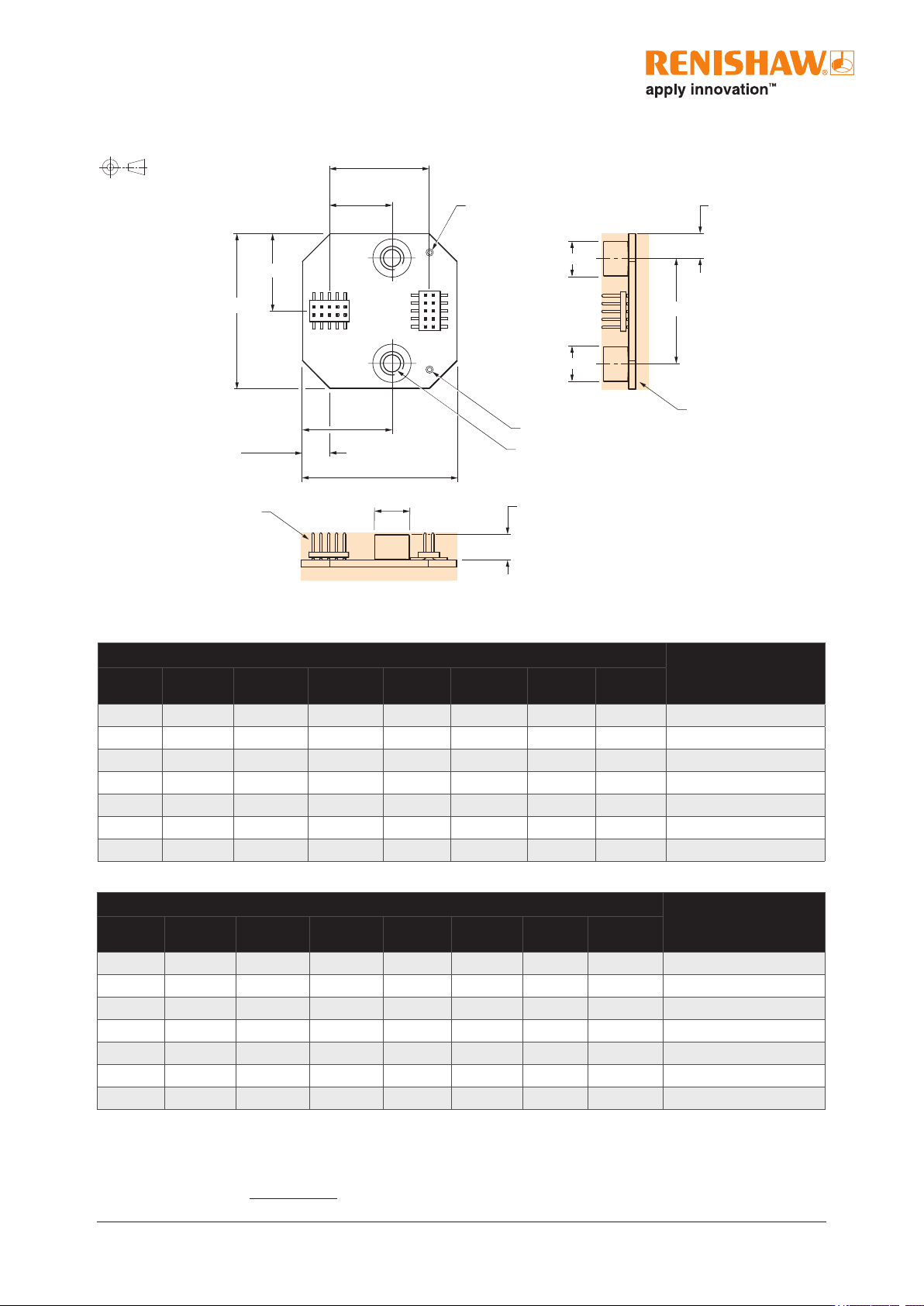
40µm system
ACi speed
20µm system
Dimensions and tolerances in mm
PCB mounting variant dimension drawing
16.1
10.1
25
4.5 × 45°
25
4
4
5.6
5.6
12.5
17
2 mounting holes M3 through
CAL pad
CAL pad
Component area
Component area
5.6
14.5
Angular speed
Angular speed depends on disc optical diameter – use the following equation to convert to rev/min:
Angular speed (rev/min) =
V × 1000 × 60
p D
where V = maximum linear speed (m/s) and D = optical diameter (mm)
Maximum speed (m/s)
Lowest recommended
counter input frequency
(MHz)
0020
(2 µm)
0040
(1 µm)
0080
(0.5 µm)
0100
(0.4 µm)
0200
(0.2 µm)
0400
(0.1 µm)
1000
(40 nm)
2000
(20 nm)
13 13 13 11.6 6 - - -
40
13 13 8 6.4 3.2 - - -
20
- - - - - 0.7 0.26 0.12
12
13 8 4 3.2 1.6 - - -
10
- - - - - 0.36 0.12 0.06
6
8 4 2 1.6 0.8 - - -
5
- - - - - 0.24 0.08 0.04
4
Maximum speed (m/s)
Lowest recommended
counter input frequency
(MHz)
0020
(1 µm)
0040
(0.5 µm)
0080
(0.25 µm)
0100
(0.2 µm)
0200
(0.1 µm)
0400
(50 nm)
1000
(20 nm)
2000
(10 nm)
6.5 6.5 6.5 5.8 3 - - -
40
6.5 6.5 4 3.2 1.6 - - -
20
- - - - - 0.35 0.13 0.06
12
6.5 4 2 1.6 0.8 - - -
10
- - - - - 0.18 0.06 0.03
6
4 2 1 0.8 0.4 - - -
5
- - - - - 0.12 0.04 0.02
4