L-9517-9563-06-A_Data_sheet_ATOM_en.pdf - 第18页
18 A TOM miniature encoder system Ri speed Cloc ked outputs Ri0100, Ri0200 and Ri0400 interfaces ha ve cloc ked outputs. Customers must ensure they comply with the lo west recommended counter input frequency . Non-c lock…
17 ATOM miniature encoder system
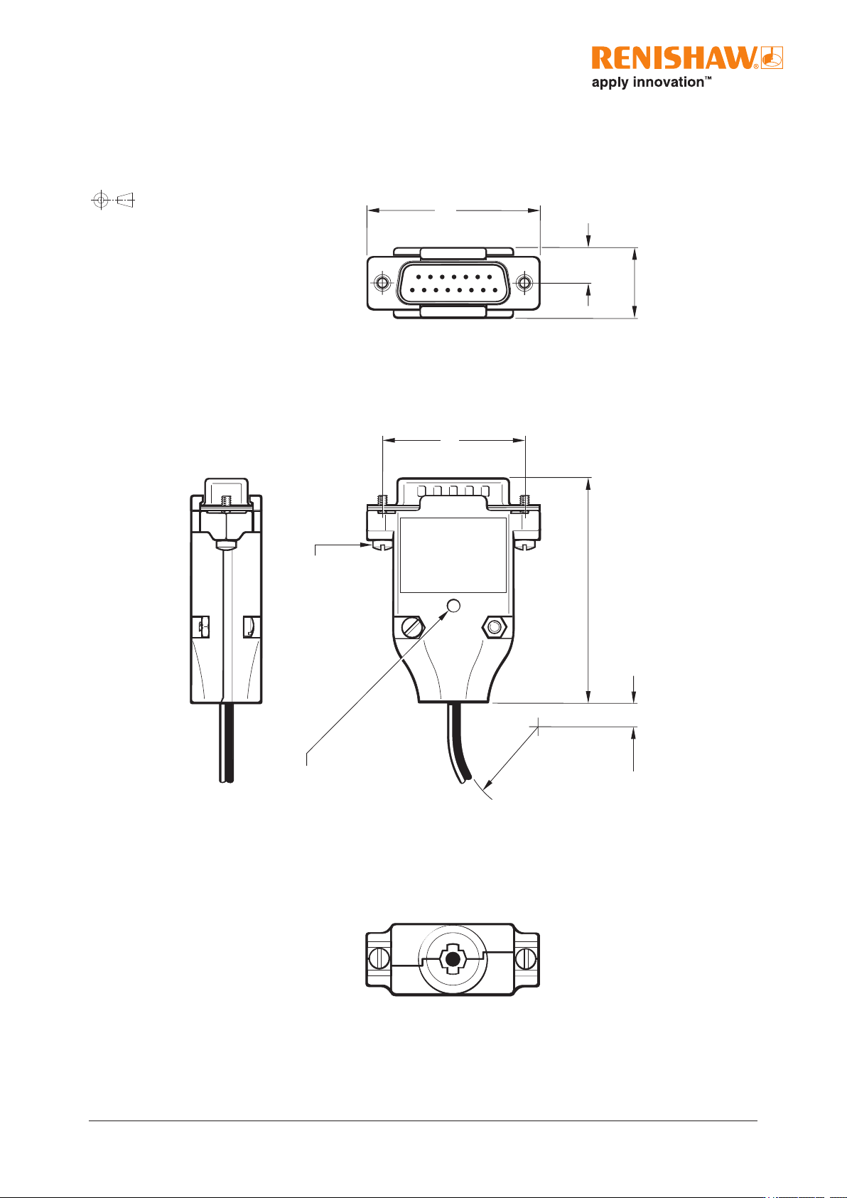
15
1
8
6 min
16
40
33.3
R > 20 Dynamic bend radius
R > 10 Static bend radius
8
4-40 unc × 2
52
CAL / AGC push button switch access hole Ø3.15
Dimensions and tolerances in mm
Ri interface
Dimension drawing
18 ATOM miniature encoder system
Ri speed
Clocked outputs
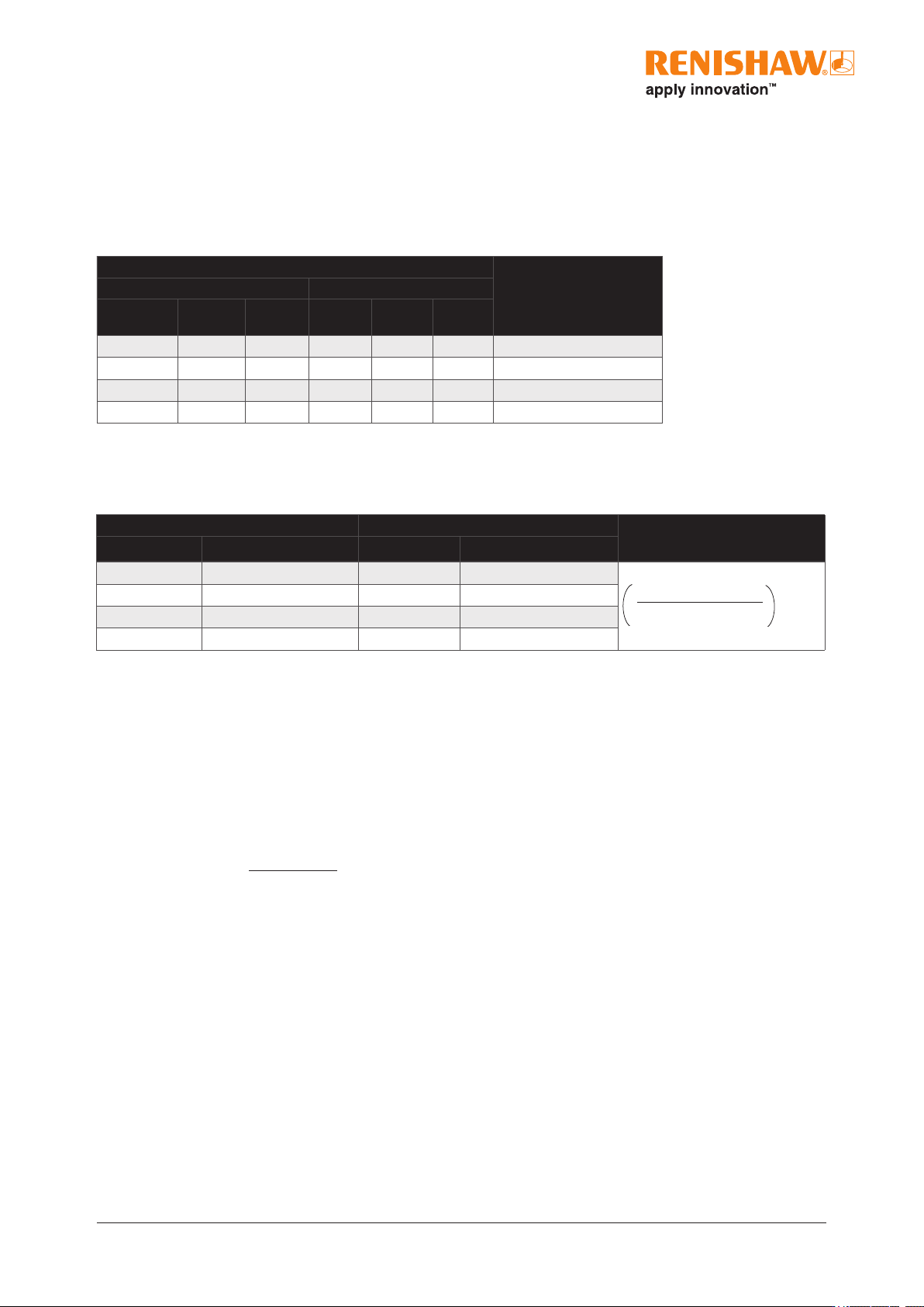
Ri0100, Ri0200 and Ri0400 interfaces have clocked outputs.
Customers must ensure they comply with the lowest recommended counter input frequency.
Non-clocked outputs
Ri0004, Ri0008, Ri0020 and Ri0040 interfaces have non-clocked outputs.
Angular speed
Angular speed depends on disc optical diameter – use the following equation to convert to rev/min:
Angular speed (rev/min) =
V × 1000 × 60
p D
where V = maximum linear speed (m/s) and D = optical diameter (mm)
Analogue outputs
40µm system - 20m/s (−3dB)
20µm system - 10m/s (−3dB)
Maximum speed (m/s)
Lowest recommended
counter input frequency
(MHz)
20 µm system 40 µm system
0100
(0.2 µm)
0200
(0.1 µm)
0400
(50 nm)
0100
(0.4 µm)
0200
(0.2 µm)
0400
(0.1 µm)
- 0.8 0.4 - 1.6 0.8
12
- 0.5 0.25 - 1 0.5
10
0.8 0.4 0.2 1.6 0.8 0.4
6
0.5 0.25 0.12 1 0.5 0.24
4
20 µm system 40 µm system
Lowest recommended counter
input frequency (MHz)
Interface type Maximum speed (m/s) Interface type Maximum speed (m/s)
0004 (5 µm) 10 0004 (10 µm) 20
0008 (2.5 µm) 10 0008 (5 µm) 20
0020 (1 µm) 10 0020 (2 µm) 20
0040 (0.5 µm) 10 0040 (1 µm) 20
Encoder velocity (m/s)
Resolution (µm)
× 4
safety
factor
19 ATOM miniature encoder system
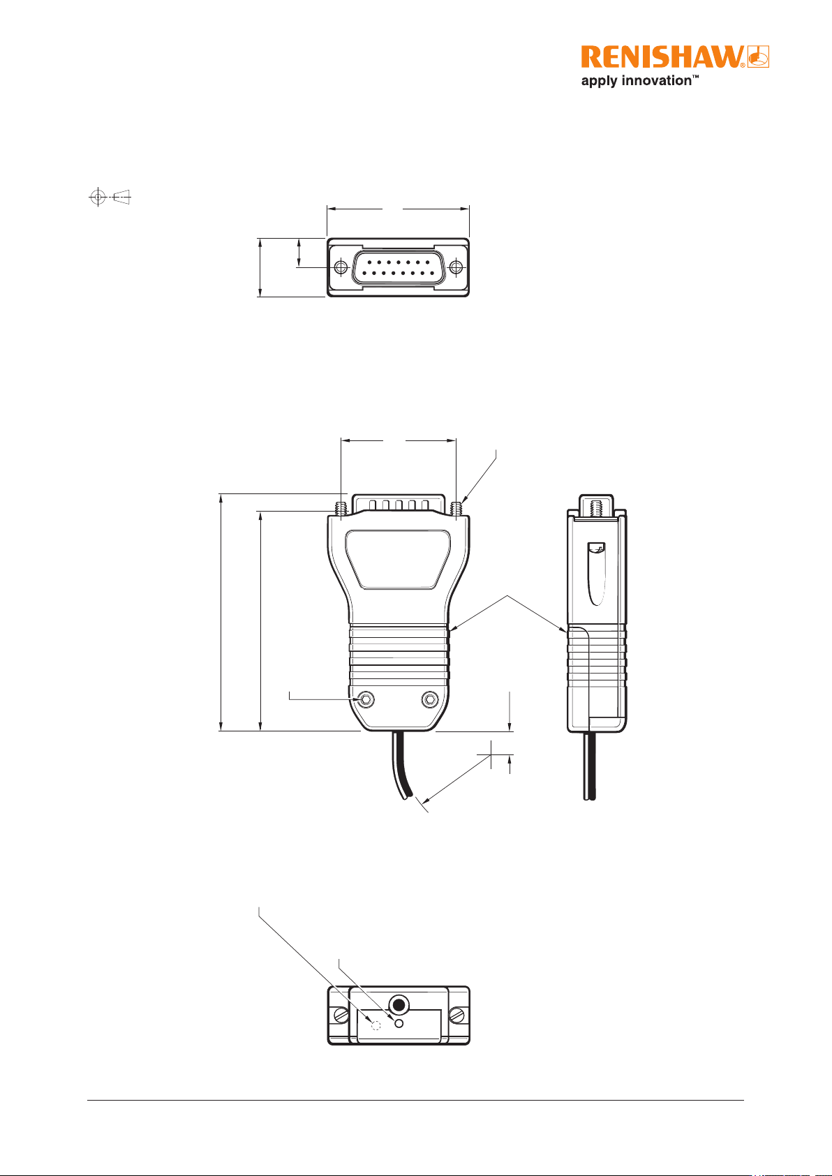
15
1
8
9
Ti interface
Dimension drawing
16
4-40 unc × 2
8
40
6 min
62
67
CAL / AGC push switch
access hole Ø2.4
R > 20 Dynamic bend radius
R > 10 Static bend radius
Cover plate
Requires 2mm hex key
Diagnostic LED
(Ti0004–Ti20KD)
33.3
Dimensions and tolerances in mm