L-9517-9563-06-A_Data_sheet_ATOM_en.pdf - 第23页
23 A TOM miniature encoder system General specications P ower supply 1 5 V ±10% A TOM readhead typically < 50 mA A TOM with A Ci typically < 100 mA A TOM with Ri typically < 100 mA A TOM with Ti typically <…
22 ATOM miniature encoder system
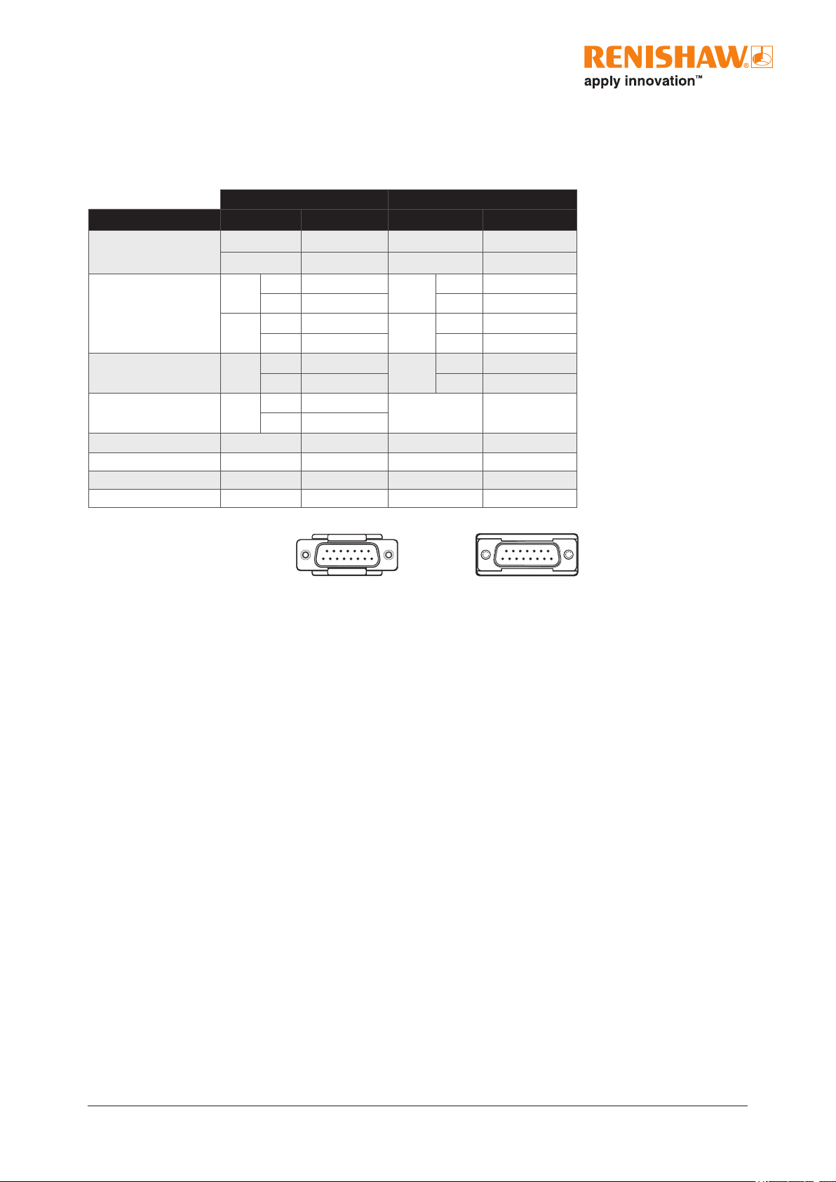
Interface signals
Ri and Ti interfaces
15
1
8
9
Ri connector
Ti connector
15
1
8
9
1
All power connections should be used either to minimise voltage drop down the cable or incorporate voltage sensing.
2
The alarm signal can be output as a line driven signal or 3-state. Select the preferred option at time of ordering.
Digital Analogue
Function Signal Pin Signal Pin
Power
1
5 V 7, 8 5 V 4, 5
0 V 2, 9 0 V 12, 13
Incremental signals
A
+ 14
V
1
+ 9
− 6 − 1
B
+ 13
V
2
+ 10
− 5 − 2
Reference mark Z
+ 12
V
0
+ 3
− 4 − 11
Alarm
2
E
+ 11
- -
− 3
Set-up X 1 V
X
6
Remote CAL - - CAL 14
Shield - Case - Case
Do not connect - 10, 15 - 7, 8, 15
23 ATOM miniature encoder system
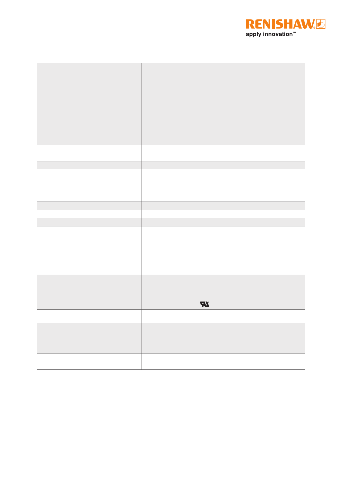
General specications
Power supply
1
5V ±10% ATOM readhead typically < 50 mA
ATOM with ACi typically < 100 mA
ATOM with Ri typically < 100 mA
ATOM with Ti typically < 200 mA
For analogue outputs a further 10mA in total will be drawn when terminated
with 120R.
For digital outputs a further 25mA per channel pair (eg A+, A−) will be drawn
when terminated with 120R.
Power from a 5Vdc supply complying with the requirements for SELV of
standard IEC60950-1.
Ripple 200mVpp maximum@frequency up to 500kHz
Temperature Storage −20°C to +70°C
Operating 0°C to +70°C
Humidity 95% relative humidity (non-condensing) to IEC60068-2-78
Sealing Cable variant IP40
FPC variant IP20 (with lid tted)
Ri interface IP20
Ti interface IP20
Acceleration (system) Operating 400m/s², 3axes
Shock (system) Operating 1000m/s², 6ms, ½sine, 3axes
Vibration Operating 100m/s² max @ 55Hz to 2000Hz, 3axes
Mass Cable readhead 4g
FPC readhead 2.3g
Cable 18g/m
Ti interface 100g
Ri interface 70g
ACi interface 4g
Readhead cable 10 core, high ex, EMI screened cable, outside diameter 3.5mm maximum
Flex life >20 × 10
6
cycles at 20mm bend radius, maximum length 5m.
(Extension cable up to 25m when using Renishaw approved extension cable)
UL recognised component
FPC cable 16 core, 0.5mm pitch, maximum exposed conductor length 2.5mm,
maximumlength 1m
Connector options Cable variants Interboard connector compatible with the Ri, Ti and ACi (cable variant)
interfaces
15-way, D-type connector
FPC 16 core, 0.5mm pitch, compatible with ACi (FPC variant)
Typical SDE (analogue) 20µm version <±75nm
40µm version <±120nm
1
Current consumption gures refer to unterminated systems.
24 ATOM miniature encoder system
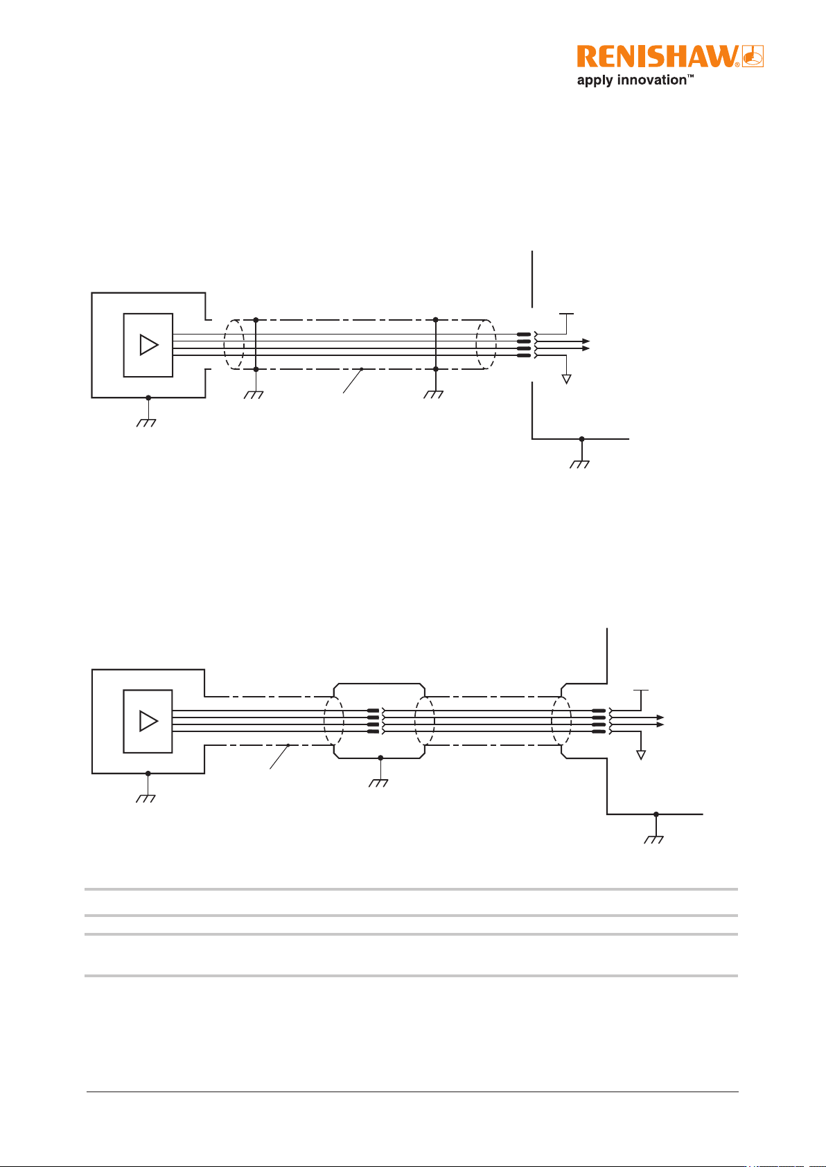
Electrical connections
Grounding and shielding
Cable readhead
Shield
Connector / interface
Customer electronics
IMPORTANT: The shield should be connected to the machine earth (Field Ground).
NOTE: Maximum cable length between interface and customer electronics is 25m for ACi and Ri and 50m for Ti depending on
clocked output.
FPC readhead
FPC cable
Shield
(recommended)
Output signals
5 V
0 V
ACi / customer electronics
For more information on FPC refer to the installation guide.
Output signals
5 V
0 V