L-9517-9563-06-A_Data_sheet_ATOM_en.pdf - 第7页
7 A TOM miniature encoder system For further information on the use of RKLF scale for partial arc applications refer to the RKL partial arc scale data sheet (Renishaw par t no. L-9517-9897). Dimensions and tolerances in …
6 ATOM miniature encoder system
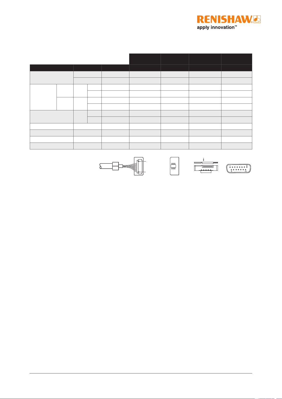
Readhead output signals
1
All power connections can be used either to minimise voltage drop down the cable or incorporate voltage sensing.
2
Only available on interboard connector.
15 way D-type plug
Interboard
connector
1
2
13
14
FPC
connection
Pin 1
JST
connector
Pin 1
Pin 12
JST
2
(on interboard)
Interboard
connector (T)
FPC
(F)
15-way D-type
(D)
Function Signal Colour Pin Pin Pin Pin
Power
1
5 V Brown 11 4 9, 10 4, 5
0 V White 5 13 3, 6, 11, 14 12, 13
Incremental Cosine
V
1
+ Red 4 9 5 9
− Blue 3 5 4 1
Sine
V
2
+ Yellow 7 12 2 10
− Green 6 14 1 2
Reference mark
V
0
+ Violet 10 2 13 3
− Grey 9 8 12 11
Set-up V
X
Clear 12 6 16 6
Remote CAL CAL Orange 8 10 15 14
Shield - Screen Cable ferrule Cable ferrule Readhead body Case
Do not connect - - 1, 2 1, 3, 7, 11 7, 8 7, 8, 15
Maximum speed
40µm readhead - 20m/s (−3dB)
20µm readhead - 10m/s (−3dB)
7 ATOM miniature encoder system
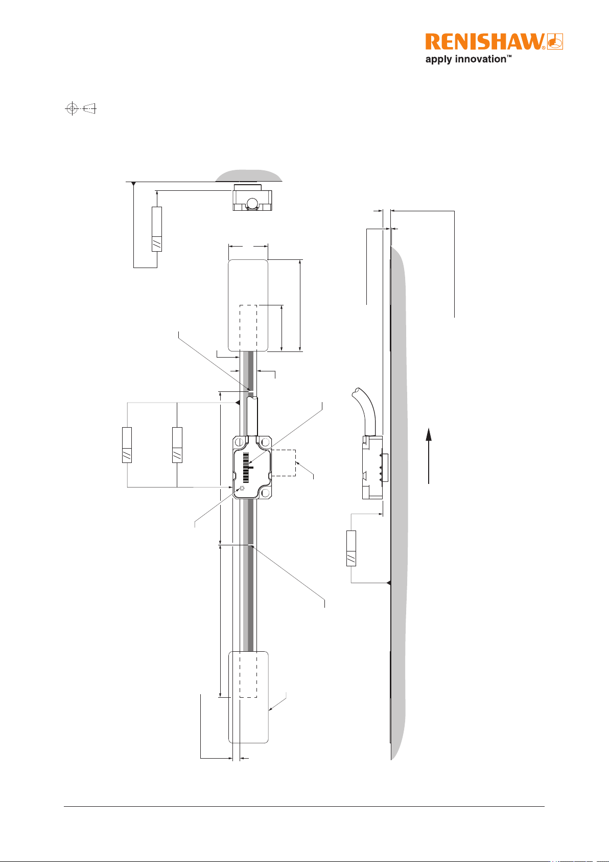
For further information on the use of RKLF scale for partial arc applications refer to the RKL partial arc scale data sheet (Renishaw part no. L-9517-9897).
Dimensions and tolerances in mm
RKLF tape scale installation drawing
0.36
0.18
(Roll tol. ±1°)
40 µm version
(Yaw tol. ±1°)
20 µm version
(Yaw tol. ±0.5°)
Scale datum edge
Reference mark
Reference mark
Set-up LED
Offset 2.02 ±0.25
50
50
Scale thickness 0.15
(including adhesive)
0.36
(Pitch tol. ±1°)
Calibration rideheight:
2.5 ±0.08 (40 µm version)
2.5 ±0.04 (20 µm version)
Operating rideheight:
2.5 ±0.11 (40 µm version)
2.5 ±0.055 (20 µm version)
Forward direction of readhead
relative to scale
0.22
FPC cable
Readhead /scale orientation
15
30
13
End clamp
(Pair A-9523-4015)
6
For detailed installation drawings refer to www.renishaw.com/atomdownloads.
8 ATOM miniature encoder system
1
20µm not suitable for partial arc applications.
2
Only selected reference mark is bi-directionally repeatable.
3
Ensure that the scale and end clamps are installed following the installation process described in the ATOM
™
linearencodersystem
installation guide (Renishaw part no. M-9696-9723).
4
Maximum recommended axis length 1m for 20μm systems.
5
To limit maximum tension in the scale (CTE
substrate
− CTE
scale
) × (T
use extreme
− T
install
) ≤550μm/m where CTE
scale
= ~10.1μm/m/°C.
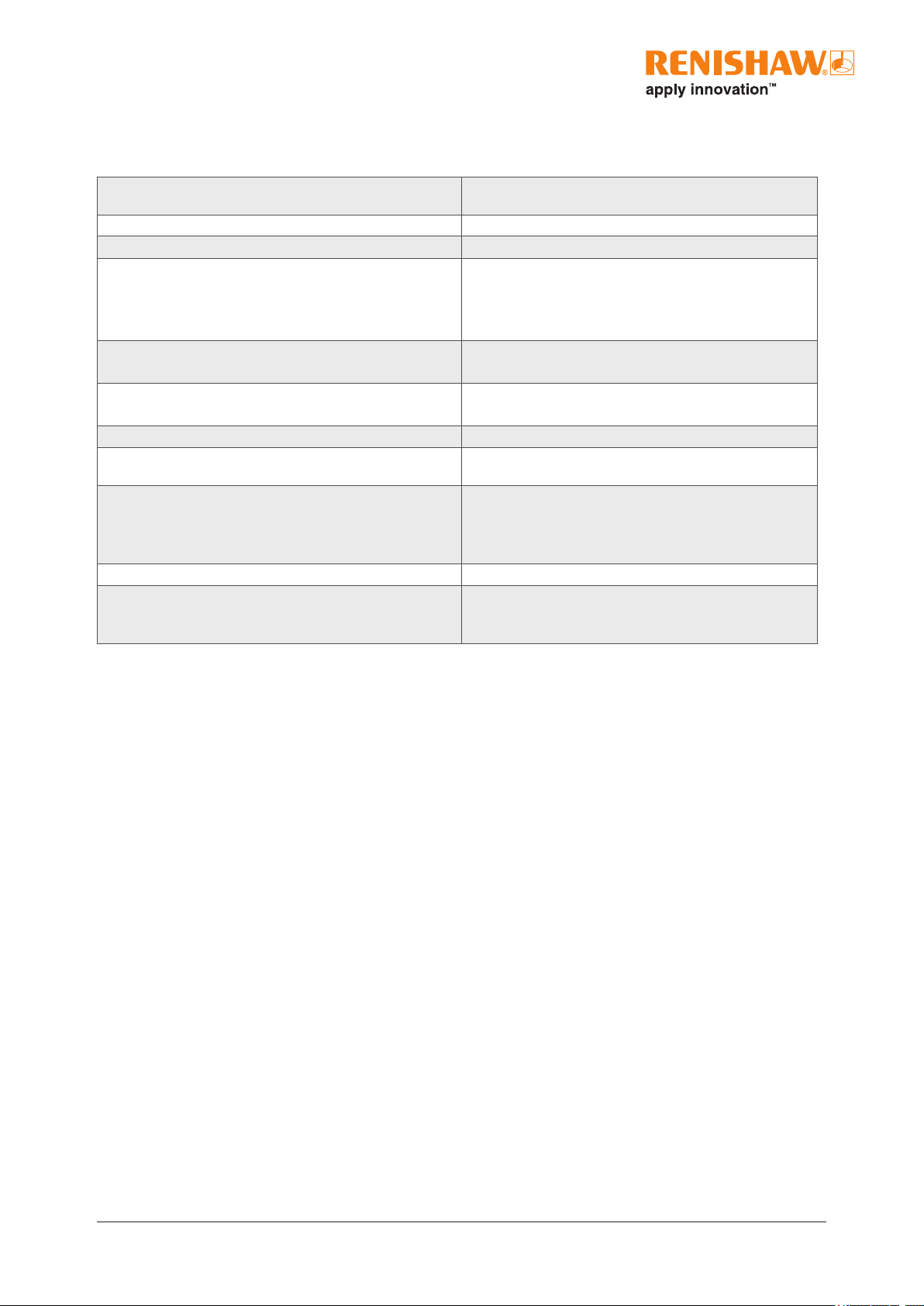
RKLF technical specications
Material Hardened and tempered martensitic stainless steel tted with
a self-adhesive backing tape
Form (H × W) 0.15mm × 6mm (including adhesive)
Scale pitch 20μm and 40μm
1
Reference mark Auto-phase optical reference mark repeatable to unit of
resolution throughout specied speed and temperature range.
Customer de-selectable reference marks at 50mm spacing.
2
Reference mark in the centre of scale for lengths <100mm.
Accuracy (at 20°C) RKLF20-S / RKLF40H-S ±5μm/m
RKLF40-S ±15μm/m
Linearity (at 20°C) RKLF20-S / RKLF40H-S ±2.5μm/m achievable with two point error correction
RKLF40-S ±3μm/m achievable with two point error correction
Installation temperature +10°C to +35°C
3
Coefcient of thermal expansion
(at 20°C)
Matches that of substrate material when scale ends xed by
epoxy mounted end clamp.
Length 20mm to 1m in 10mm increments
1m to 10m in 1m increments
4
Overall length = measuring length + 70 mm
Scale length = measuring length + 40mm
Mass 4.6g/m
End xing Epoxy mounted end clamps (A-9523-4015)
Approved epoxy adhesive (A-9531-0342)
Scale end movement typically <1μm
5