L-9517-9563-06-A_Data_sheet_ATOM_en.pdf - 第26页
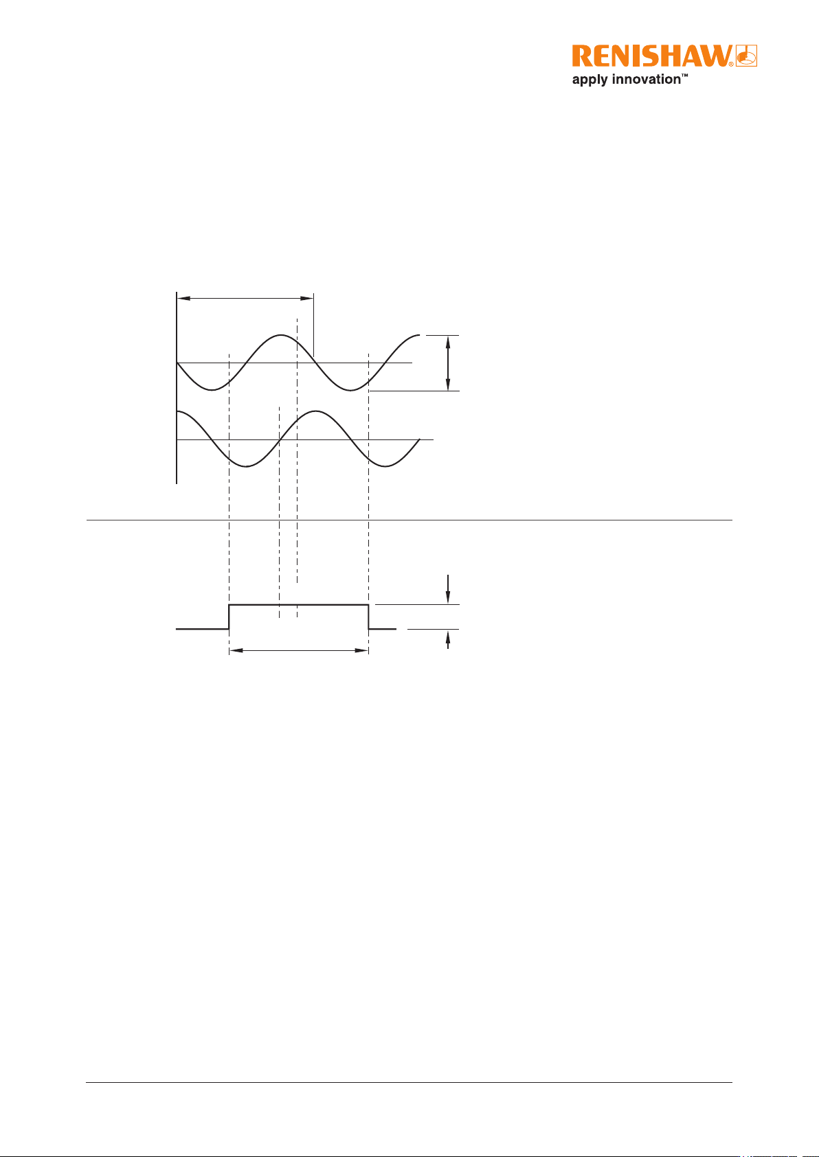
26 A TOM miniature encoder system Incremental 2 channels V 1 and V 2 differential sin usoids in quadrature, centred ~ 1.65 V (90° phase shifted) Bi-directionally repeatable . 1 Differential pulse V 0 centred on 45°. Refe…
25 ATOM miniature encoder system
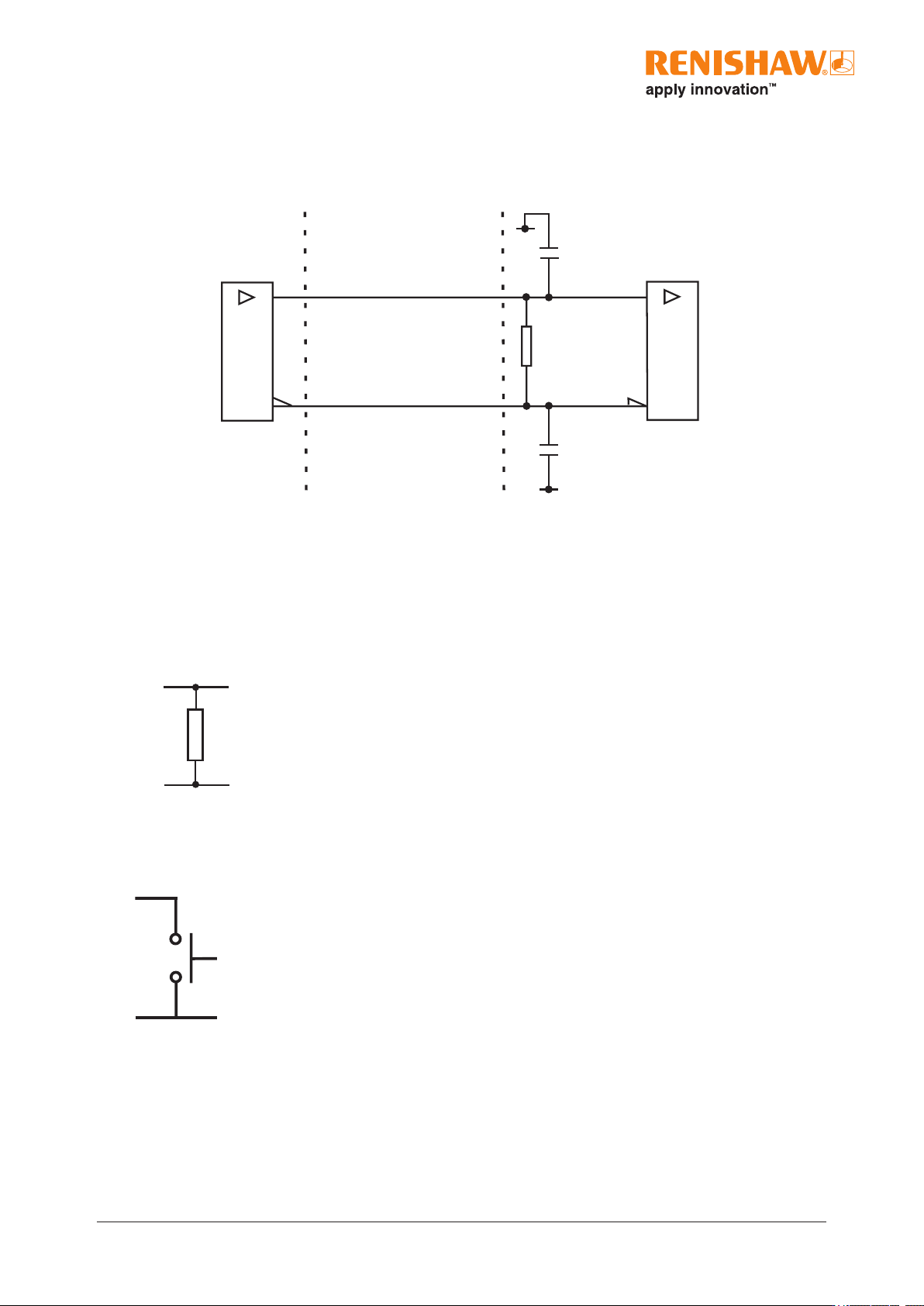
Analogue outputs
V
0
V
1
V
2
−
V
0
V
1
V
2
+
120R
Remote CAL operation
CAL
0 V
Remote operation of the CAL is possible via the CAL pin. For applications where no interface is used,
remote CAL operation is essential.
Recommended signal termination
Digital outputs
Interface
A B Z E+
Cable Z
0
= 120R
Customer
electronics
A B Z E−
120R
Standard RS422A line receiver circuitry.
Capacitors recommended for improved noise immunity.
220 pF
0 V
0 V
220 pF
26 ATOM miniature encoder system
Incremental 2 channels V
1
and V
2
differential sinusoids in quadrature, centred ~ 1.65 V (90° phase shifted)
Bi-directionally repeatable.
1
Differential pulse V
0
centred on 45°.
Reference
(V
0
+)−(V
0
−)
360° (nom)
0.7 to 1.35Vpp with green LED indication
(readhead) and 120R termination.
40 / 20 µm
(V
1
+)−(V
1
−)
(V
2
+)−(V
2
−)
0°
(after CAL)
45°
1Vpp
Differential signals V
0
+ and V
0
− centred on ~ 1.65V.
Output specications
Analogue output signals
All ATOM readheads and Ri and Ti analogue interfaces
1
Only calibrated reference mark is bi-directionally repeatable.
27 ATOM miniature encoder system
Voltage at V
X
3.3V (nom)
50% 70% 100%0
0
Signal level
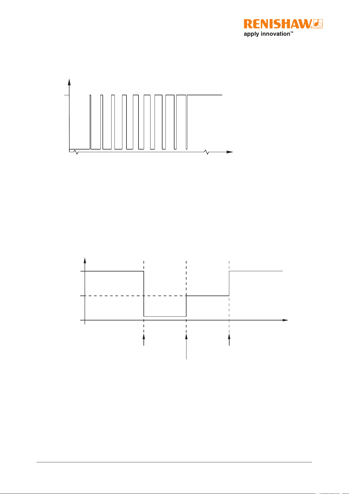
Between 50% and 70% signal level, V
X
is a duty cycle.
Time spent at 3.3V increases with incremental signal level.
At >70% signal level V
X
is nominal 3.3V.
Set-up
During normal operation
Voltage at V
X
Normal operation Normal operationReference
mark
calibration
3.3V
1.65 V
0 V
Start of
calibration
routine
End of
incremental
calibration routine
End of
calibration
routine
Incremental
calibration
>70% signal
During CAL routine
>70% signal