IPC J-STD-003B.pdf - 第33页
6 NOTES 6.1 Correction for Buoyancy For the wetting balance to obtain wetting force values that are comparable with one another , it is necessary to correct for the variability in test specimen sizes, particularly width …
5 EVALUATION AIDS
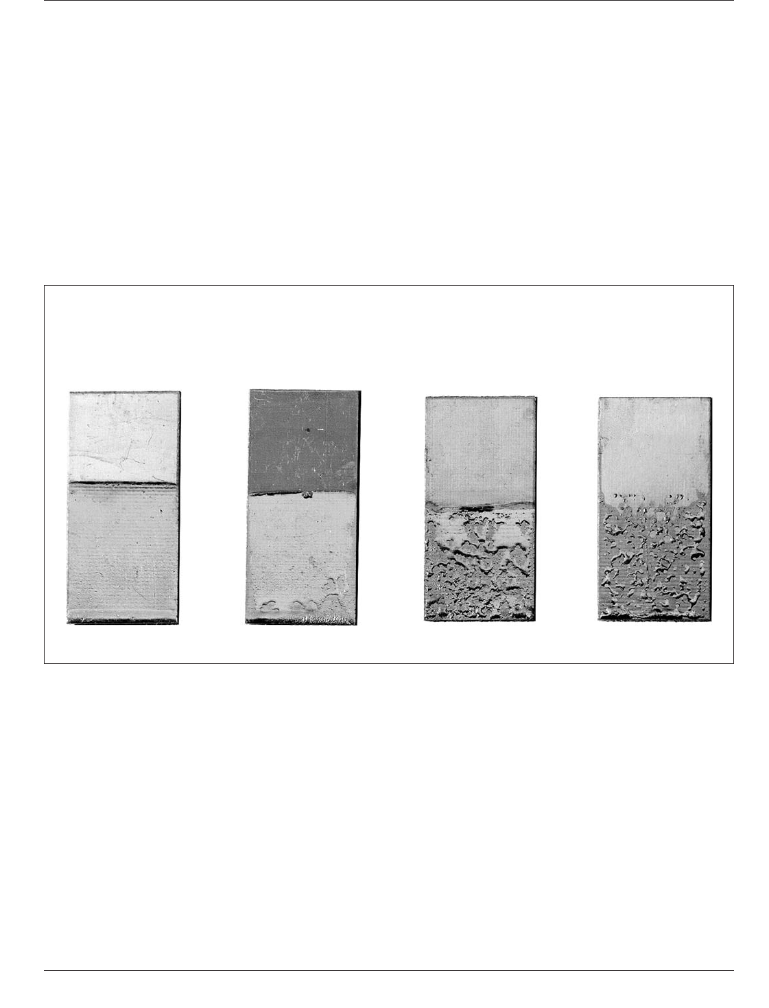
5.1 Evaluation Aids – Surface
As an aid to evaluation of
the test results (see Figure 5-1). This aid is to be used pri-
marily to illustrate types of defects rather than percentage
of area covered.
5.2 Evaluation Aids – For Class 3 Plated-Through
Holes
Profile views of acceptable conditions are pre-
sented in Figure 4-5 for aid in visualizing all the common
conditions. The following are also acceptable conditions
for specific cases:
• Solderability acceptance for plated-through holes with
aspect ratios greater than 5:1 (board thickness: hole diam-
eter) shall be agreed upon by user and vendor.
• Depressed fillets in holes are acceptable under the follow-
ing condition: the solder in partially filled holes must
exhibit a contact angle less than 90 ° relative to the hole
wall (see Figure 4-5 and 4-6).
• All holes less than 1.5 mm [0.0591 in] diameter shall
retain a solder plug after solidification. Holes greater than
1.5 mm [0.0591 in] shall not be rejected for failure to
retain a full solder plug provided that the entire barrel of
the hole and the surface of the top land have been wetted
with solder (see Figures 4-5 and 4-6).
Preferred
Wetting
Small Amount
of Dewetting
Complete
Dewetting Nonwetting
IPC-003b-5-1
Figure 5-1 Aid to Evaluation
IPC J-STD-003B March 2007
22
Copyright Association Connecting Electronics Industries
Provided by IHS under license with IPC
Not for Resale
No reproduction or networking permitted without license from IHS
--`,,```,,,,````-`-`,,`,,`,`,,`---
//^:^^#^~^^"^~"^"^:$^~#:"#:$@:~^"$^:#*~^$^~:^#*^^:^^*\\

6 NOTES
6.1 Correction for Buoyancy
For the wetting balance to
obtain wetting force values that are comparable with one
another, it is necessary to correct for the variability in test
specimen sizes, particularly width and thickness. This is
done by correcting for the volume of the sample immersed
in the solder. The following formula may be used to calcu-
late the buoyant force correction:
F
b
= ρ gV
where:
ρ = Density of solder at 235 °C (8.12 g/cm) for Sn60/
Pb40 Alloy
ρ = Density of solder at 255 °C (7.41 g/cm) for SAC305
Alloy
g = Acceleration of gravity (981 cm/sec
2
)
V = Immersed volume of the test specimen (cm
3
)
= width x thickness x immersion depth, for example.
When the buoyancy force is calculated, it should be used
to correct the zero axis. This correction is required to
obtain both the proper measurement of wetting times, as
well as wetting forces. All measurements of wetting times
and wetting forces must be made from the corrected zero
axis. In the case of an upright curve, the new corrected zero
axis will be below the instrumental zero.
6.2 Preheat If the board test specimen does not pass the
standard solderability test then a uniform preheat of a sec-
ond test specimen may be used to determine if design/
construction has impacted the solderability test (i.e., a thick
board with heavy internal ground planes). If this referee
test specimen passes, then testing with preheat shall be the
method of choice for future testing of test specimens hav-
ing that design/construction.
6.3 Baking The occurrence of outgassing, which may
result in blowholes, measling, blisters or delamination, may
be reduced by baking the printed board prior to soldering
to eliminate moisture or solvents. Other factors, such as
conveyor speed (for wave solder testing), solder tempera-
ture, contamination content, etc., may also cause defects
and, therefore, should be analyzed if problems occur. Test
specimens should be baked in a suitable oven to remove
any absorbed moisture. Temperature and time of baking is
to be determined on an individual basis.
The time between baking and solderability testing should
be kept to a minimum (not more than 24 hours) in order to
prevent re-absorption of water vapor into the laminate
structure. The actual time delay threshold is dependent
upon ambient temperature and humidity levels.
6.4 Prebaking Printed boards should be prebaked only if
prebaking is normally used as a production procedure.
Baking should be kept to a minimum, adhering to the pro-
duction procedure, to prevent excessive oxidation and
intermetallic growth.
6.5 Safety Note Care must be taken in both usage and
storage to keep flammable solvents from sparks or flames.
See the Material Safety Data Sheets (MSDS) for all sol-
vents. All chemicals shall be handled per appropriate data
sheets, and disposed of per local regulations.
6.6 Use of Nonactivated Flux This standard specifies a
rosin-based flux with a very specific quantity of activator.
The intent of requiring the use of a specific quantity of flux
activator is to reduce the variability of test results that were
seen with pure rosin flux, enable the solderability testing of
nontin component lead metallizations, and provide a realis-
tic solderability testing safety factor by keeping the amount
of activator both fixed and less than that used for produc-
tion soldering. The benefit of using this specified activated
solderability testing flux composition was demonstrated by
extensive testing, as reported in the J-STD-002/003 Acti-
vated Solderability Test Flux Rationale Committee Letter.
6.7 Solder Contact The solder applied during the solder-
ability test must contact a feature in order for that feature
to be considered for evaluation. Small features surrounded
by a thick solder mask may prevent solder contact.
March 2007 IPC J-STD-003B
23
Copyright Association Connecting Electronics Industries
Provided by IHS under license with IPC
Not for Resale
No reproduction or networking permitted without license from IHS
--`,,```,,,,````-`-`,,`,,`,`,,`---
//^:^^#^~^^"^~"^"^:$^~#:"#:$@:~^"$^:#*~^$^~:^#*^^:^^*\\

APPENDIX A
Calculation of Maximum Theoretical
Force for a Rectangular Cross-Section
Maximum theoretical force for the test board with a ground
plane surface is calculated using the procedure of Klein
Wassink.
2
The maximum force, in units of milliNewtons
(mN), is defined as:
Force (Max. Theoretical) = (γ) (P) (cosine β) - (d)(g)(V) =
[0.4P - 0.08V] mN
where:
P = The perimeter of the test specimen in millimeters, i.e.,
the length in millimeters of the solder/printed board or
coupon pad (or hole)/air interface as measured at
maximum depth of immersion.
V = The volume in cubic millimeters of the test specimen
that resides below the solder/board air interface as
measured at the maximum depth of immersion.
γ = Surface tension of solder = 0.4 mN/mm
γ = Surface tension of Pbfree solder = 0.5 mN/mm
α = Immersion angle of the board to the horizontal surface,
i.e., α =45°
β = Wetting angle of solder to the board under optimal
conditions, i.e., β = 0, Therefore the cosine β =1
d = Density of solder at 235 °C, = 8120 kg/m
3
for Sn60/
Pb40 Alloy
d = Density of solder at 255 °C = 7410 kg/m
3
for SAC305
Alloy
g = Gravitational constant = 9.8 x 10
3
mm/s
2
Periphery and volumes Perimeter and volumes are to be
calculated using the nominal values provided by the test
board supplier and the angles and depths of immersion as
described in the specification above. The TOTAL perimeter
(the length in millimeters of all of the solder/coupon or
coupon/pad (or hole)/air interfaces on the test coupon being
immersed (e.g., if there are five pads being immersed, then
the sum of the widths of the five pads parallel to the solder
surface) is to be used. For the immersion volume, use the
volume of the portion of the test coupon pushed below the
surface of the solder and NOT the entire volume of the
whole test coupon, is to be used in this calculation. Where:
For Example:
For a tin/lead solder alloy:
Width of coupon = 0.4 mm, Length = 9.2 mm, P = wetting
perimeter = 10 mm, Immersion depth=D=0.2mm
Hence for a dip at a 90 ° angle:
V = Total volume immersed = (10 - (2 x 0.4)) mm x
0.2 mm x 0.4 mm = 0.736 mm
3
Therefore, the maximum theoretical wetting force is:
Maximum Force = (γ) (P) (cosine b) - (d) (g) (V) =
(0.4 mN/mm x 10 mm x cosine 0) - (8.12 x 10⁻⁶ kg/mm
3
x 9.8 x 103 mm/s
2
x 0.736 mm
3
) = 3.94 mN
Finally, for a 10 mm perimeter, ideal wetting force per mil-
limeter of perimeter for our sample is 0.394 mN/mm. From
Table 4.5 (or 4.6) the force measured on a test specimen in
the ‘‘preferred’’ class must be close to 0.394 mN/mm. (It
CANNOT be greater than 0.394 mN/mm.)
Theoretical force calculations are difficult for test speci-
mens with other than pads that come to the edge of the
specimen. Therefore, the best way to use the wetting bal-
ance test method is to separately set up a control value for
a ‘‘Best Possible’’ sample; and other test pieces will be
compared to this value for establishing either an acceptable
or a reject criterion.
Second Example:
The calculations for the same sample dipped into the same
solder at a 45 angle
For a tin/lead solder alloy:
Width of coupon = 0.4 mm, Length = 9.2 mm, Immersion
depth=D=0.2mm,P=wetting perimeter = 10 mm
Hence for a dip at a 45 ° angle:
V = Total volume immersed = 0.5 x 9.2 mm x 0.283 mm
x 0.283 mm = 0.368 mm
3
(The 0.5 accounts for the fact that you are only dipping at
a 45 ° angle). Remember the area of a right angle triangle
is one half times the length of the two sides that are not the
hypotenuse.) Still assuming perfect wetting (wetting angle
= 0 °) Cosine of0°=1
Therefore, the maximum theoretical wetting force is:
Maximum Force = (γ) (P) (cosine b) - (d) (g) (V) =
(0.4 mN/mm x 10 mm x cosine 0) - (8.12 x 10
-6
kg/mm
3
x9.8x10
3
mm/s
2
x 0.368 mm
3
) = 3.97 mN
Therefore, again for a 10 mm perimeter, ideal wetting force
per millimeter of perimeter for our sample 0.397 mN/mm,
slightly higher than in the previous example because the
buoyancy correction is only half the size.
2. R.J. Klein Wassink, ‘‘Soldering in Electronics,’’ 2nd Edition, Electrochemical Publications, Ayr, Scotland, 1989, pp 308-309
IPC J-STD-003B March 2007
24
Copyright Association Connecting Electronics Industries
Provided by IHS under license with IPC
Not for Resale
No reproduction or networking permitted without license from IHS
--`,,```,,,,````-`-`,,`,,`,`,,`---
//^:^^#^~^^"^~"^"^:$^~#:"#:$@:~^"$^:#*~^$^~:^#*^^:^^*\\