00193802-01.pdf - 第157页
User Manual SIPLAC E CF 6 Component han dling Software version SR.101.xx 06/2003 US Edition 6.4 Component trolley 157 It is easy to fit. Use three screws DIN 912, M8 x20 (item 3) to fix the c ompressed air supply (item 2…
6 Component handling User Manual SIPLACE CF
6.4 Component trolley Software version SR.101.xx 06/2003 US Edition
156
6.4.2 Tape container
Reels up to 19" in diameter may be used. Insert the spindles into the dividing plates as shown in
Fig. 6.5 - 2
.
PLEASE NOTE 6
We recommend that you use spindles if the tape reel diameter exceeds 7". This will ensure that
the feeders operate reliably. 6
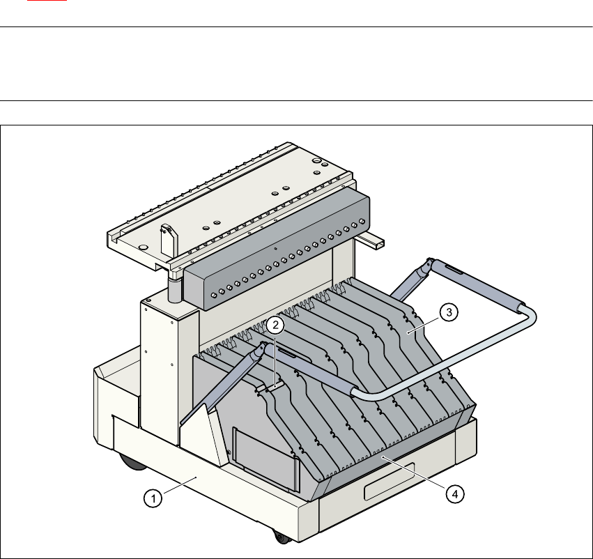
Fig. 6.4 - 2 Component trolley with tape container
(1) Component trolley
(2) Spindle
(3) Dividing plate
(4) Tape container
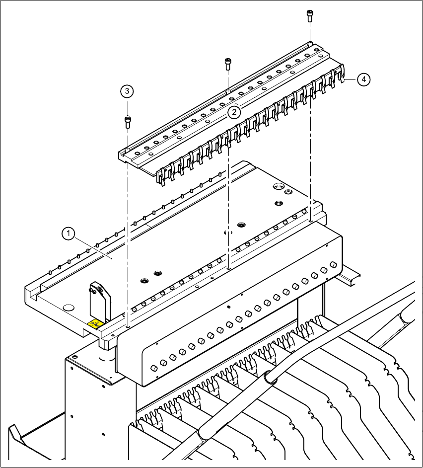
6.4.3 Compressed air supply for bulk case feeder
Bulkcase feeders require compressed air to operate. We therefore offer a compressed air supply
for bulkcase feeders as an optional extra.
User Manual SIPLACE CF 6 Component handling
Software version SR.101.xx 06/2003 US Edition 6.4 Component trolley
157
It is easy to fit. Use three screws DIN 912, M8x20 (item 3) to fix the compressed air supply (item
2) to the component feeder table (item 1). The compressed air supply has retaining clips (item 4)
on the back. These secure the bulk case feeder to the component trolley and ensure that the
compressed air supply is working properly.
Fig. 6.4 - 3 Compressed air supply for bulk case feeders
(1) component feeder table
(2) Compressed air supply for bulk case feeders
(3) Screw DIN 912, M8x20
(4) Retaining clamp
6 Component handling User Manual SIPLACE CF
6.4 Component trolley Software version SR.101.xx 06/2003 US Edition
158
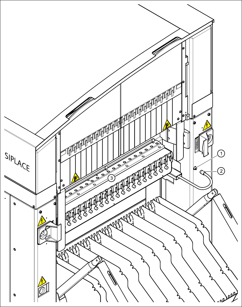
Fig. 6.4 - 4 Connecting the compressed air supply for bulk case feeders
6
(1) Coupling connector for compressed air
(2) Coupling socket with supply hose
(3) Compressed air supply distributor for bulk case feeders