00193802-01.pdf - 第90页
3 Technical data User Manual SIP LACE CF 3.9 Placement heads Software version SR. 101.xx 06/2003 US Edition 90 3.9 Placem ent heads 3.9.1 6-segm ent Collect &Place head 3.9.1.1 S tructure 3 Fig. 3.9 - 1 Structure of …

User Manual SIPLACE CF 3 Technical data
Software version SR.101.xx 06/2003 US Edition 3.8 Gantry
89
3.8.3 Technical data for the X axis
3
3.8.4 Structure of the Y axis
The Y axis essentially consists of the following main modules:
– Y axis three-phase AC servomotor
– Y axis toothed belt
– Y axis guide system
– Y axis measuring system
The Y axis is driven by a three-phase AC servomotor. An anti-crash circuit limits the gantry tra-
versing path.
3.8.5 Technical data for the Y axis
3
Drive Three-phase AC servomotor/toothed belt
Maximum speed 2.5 m/sec.
Traversing path 620 mm
Distance measuring system Metal linear scale
Scale length 646 mm
Resolution 1.0 µm
Drive Three-phase AC servomotor/toothed belt
Maximum speed 2.5 m/sec.
Traversing path 910 mm
Distance measuring system Metal linear scale
Scale length 970 mm
Resolution 1.0 µm
3 Technical data User Manual SIPLACE CF
3.9 Placement heads Software version SR.101.xx 06/2003 US Edition
90
3.9 Placement heads
3.9.1 6-segment Collect&Place head
3.9.1.1 Structure
3
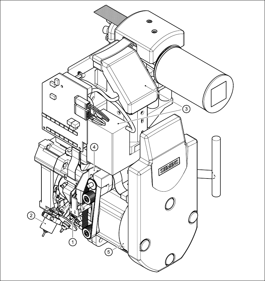
Fig. 3.9 - 1 Structure of the 6-segment Collect&Place head with standard component
vision module - part 1
(1) Star with 6 sleeves (4) Z axis drive
(2) Motor for "Reject" valve adjustment drive (5) Star motor
(3) Component camera
User Manual SIPLACE CF 3 Technical data
Software version SR.101.xx 06/2003 US Edition 3.9 Placement heads
91
3
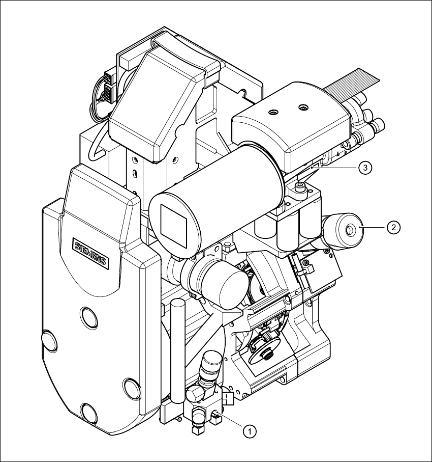
Fig. 3.9 - 2 Structure of the 6-segment Collect&Place head with standard component
vision module - part 2
3
(1) Forced air valve
(2) Turning station
(3) Vacuum generator