00193802-01.pdf - 第58页
2 Operational safety User Manual SIPLACE CF 2.8 Energy state of the machine af ter switching off at the main power switch Software version SR .101.xx 06/2003 US Edition 58 2.8 Energy state of the mach ine af ter switchin…

User Manual SIPLACE CF 2 Operational safety
Software version SR.101.xx 06/2003 US Edition 2.7 Disabling the compressed air supply and discharging the pressure
57
main switch and disconnect it from the power supply. 2
The compressed air working pressure is set to 0.52 MPa (5.2 bar). It may fluctuate between 0.5
MPa (5.0 bar) and 0.53 MPa (5.3 bar). The position of the compressed air unit is indicated by
item 5 in Fig. 2.7 - 1
. The compressed air supply to the machine can be interrupted using the
shutoff valve (item 1 in Fig. 2.7 - 1
).
– You must remove the cover plate to use the shut-off valve.
– Turn the lever on the shut-off valve (item 1 in Fig. 2.7 - 1
) from the vertical to the horizontal
position.
– Watch the working pressure gauge (item 2 in Fig. 2.7 - 1
) and the pressure gauge for the com-
pressed air supply to the stopper (item 4 in Fig. 2.7 - 1
). When the automatic placement system
is switched on, the pressure discharges to 0 MPa (0 bar) within 1 minute.
2 Operational safety User Manual SIPLACE CF
2.8 Energy state of the machine after switching off at the main power switch Software version SR.101.xx 06/2003 US Edition
58
2.8 Energy state of the machine after switching off at
the main power switch
WARNING 2
Automatic placement systems from the SIPLACE family are powered with 3 x 400 V or 3 x
208 VAC (U.S.A. version) ± 5 %, 50/60 Hz mains voltage. This means that parts of the system
carry potentially fatal voltages - even when switched off at the main switch. Death, serious injury
or considerable damage may result if these automatic placement systems are handled incor-
rectly. Always follow the applicable accident prevention and DIN regulations (particularly
EN 60204, part 1). The guards over the control and servo units must ONLY be opened by appro-
priately qualified and trained personnel. 2
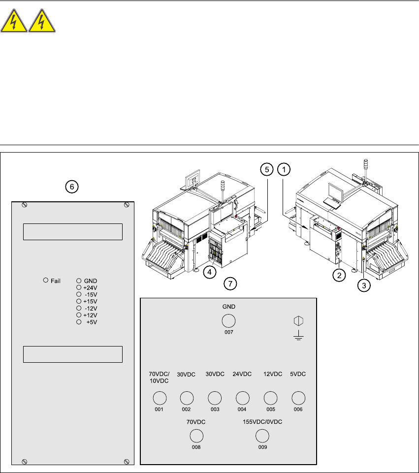
Fig. 2.8 - 1 Position of the control unit, servo unit, main switch, service socket and compressed
air unit in the placement system
(1) Main switch Q1< (5) Control unit
(2) Compressed air unit (6) Power supply in the control unit
(3) Service socket (7) Measuring unit, servo unit
(4) Servo unit
unswitched switched
User Manual SIPLACE CF 2 Operational safety
Software version SR.101.xx 06/2003 US Edition 2.8 Energy state of the machine after switching off at the main power switch
59
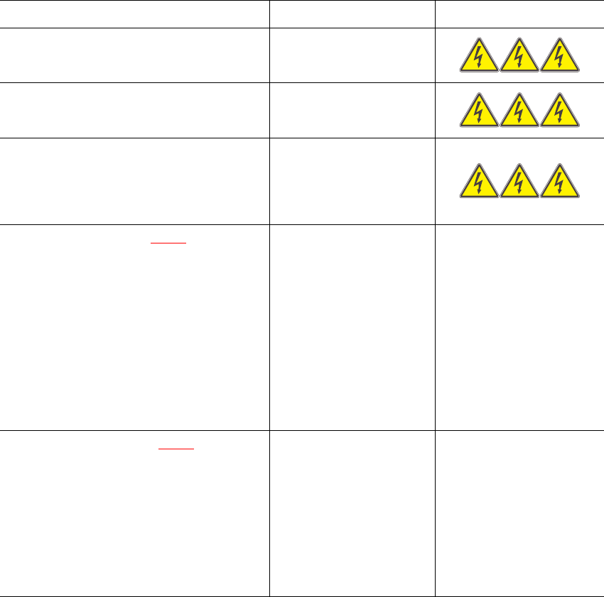
2.8.1 Placement system switched off at the main power switch, but still connected
The following table specifies the voltages of modules when the automatic placement system is
switched off at the main switch, but still connected to the mains supply.
2
2.8.2 Placement system switched off at the main power switch and disconnected
The automatic placement system is unpowered, apart from slight residual voltages in the servo
unit.
Assembly Voltage
Main power filter Z1
Terminals L1, L2, L3
3 x 400 VAC (3 x 208
VAC)
Service socket
230 VAC(115 VAC)
Main switch Q1
Terminals L1, L2, L3
Terminals T1, T2, T3
3 x 400 VAC (3 x 208
VAC)
0 VAC
Servo unit (item 7 in Fig. 2.8 - 1
)
Test socket 001
Test socket 002
Test socket 003
Test socket 004
Test socket 005
Test socket 006
Test socket 008
Test socket 009
GND 007
< 12 VDC
< 12 VDC
< 12 VDC
0 VDC
0 VDC
0 VDC
< 12 VDC
< 12 VDC
Control unit (item 6 in Fig. 2.8 - 1
)
Test socket 5 V
Test socket + 12 V
Test socket – 12 V
Test socket + 15 V
Test socket – 15 V
Test socket + 24 V
GND
0 VDC
0 VDC
0 VDC
0 VDC
0 VDC
0 VDC
Tab. 2.8 - 1 Voltages of assemblies when the automatic placement system is switched off at the main switch,
but still connected to the main power