00193802-01.pdf - 第82页
3 Technical data User Manual SIP LACE CF 3.6 Controls Software version SR. 101.xx 06/2003 US Edition 82 3.6.2 Description All the c ontrols can be reac hed b y a 1.60 m tall person . Main power switch The main power sw i…
User Manual SIPLACE CF 3 Technical data
Software version SR.101.xx 06/2003 US Edition 3.6 Controls
81
3
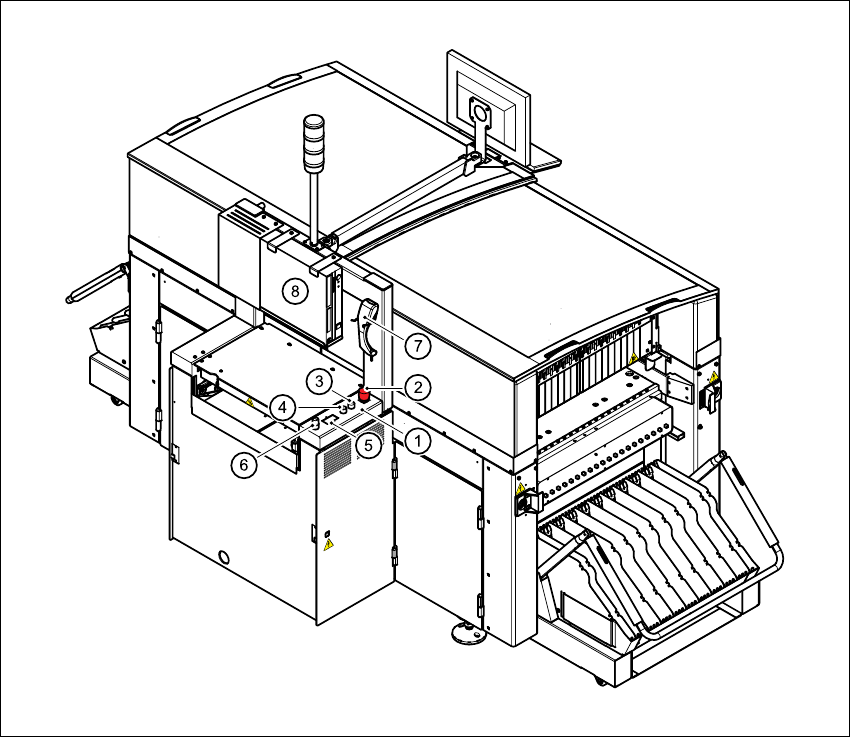
Fig. 3.6 - 2 Overview of the modules - controls - part 2
3
(1) Operator panel, output conveyor
(2) Emergency stop button
(3) Start button (white)
(4) Stop button (black)
(5) Component counter
(6) Key-operated switch
(7) Component barcode reader
(8) Station computer

3 Technical data User Manual SIPLACE CF
3.6 Controls Software version SR.101.xx 06/2003 US Edition
82
3.6.2 Description
All the controls can be reached by a 1.60 m tall person.
Main power switch
The main power switch is used to switch the power supply to the placement machine on and off.
RISK OF DEATH
Some parts inside the placement system carry potentially lethal voltages - even when switched
off at the main switch. 3
Key switch
In normal mode, the key switch is set to "0". The key should be removed and kept in a safe place.
It must only be turned to position "I" (set-up mode) by authorized personnel, and then only for
certain maintenance and servicing work.
Stop button
This button is used to stop the placement machine.
Start button
This button starts the placement machine after it has been switched on or after faults have been
eliminated.
Emergency stop button
The emergency stop button latches in the ON position when pressed. The power supply to the
gantry axes, the components changeover tables, conveyors, and used tape cutters is interrupted
and the voltage supplied to the star axes of the placement heads is reduced. Turn the button to
release it.
Component counter
The component counter displays the number of components processed.
Station computer, monitor and keyboard
The monitor and keyboard are mounted on a rotatable bracket. The station computer is a desk-
top model. It has a Pentium processor and runs the WINDOWS XP operating system. The
SIPLACE graphical user interface, which is based on the Windows standard, is used to operate
and monitor the placement system. A 15" color monitor with a resolution of 1024 x 768 pixels

User Manual SIPLACE CF 3 Technical data
Software version SR.101.xx 06/2003 US Edition 3.6 Controls
83
provides the screen display. The ultra-flat IBM-compatible PC keyboard incorporates a trackball
for controlling the mouse.
Indicator lamps
The sequence of colors is white - green - white. It signals operating statuses and malfunctions of
the placement machine (see chapter 5
).
Component barcode reader
The Datalogic DL910 component barcode reader is attached to a bracket on the output side of
the machine. It enables the components to be set up and topped up quickly and reliably.
3.6.3 Ergonomic arrangement of the controls
Figure 3.6 - 1 on page 80 provides an overview of the position of the controls. They are subdi-
vided into the following groups:
Operating panel on the PCB input side with
– start button
– stop button
– emergency stop button
– main power switch
Operating panel on the PCB output side with
– emergency stop button
– start button
– stop button
– component counter
– key-operated switch
– component barcode reader
Pivoting bracket with
– monitor and
– keyboard