00193802-01.pdf - 第88页
3 Technical data User Manual SIP LACE CF 3.8 Gantry Software ve rsion SR.101.xx 06/2003 US Edition 88 3.8.2 St ructure of th e X axis 3 Fig. 3.8 - 2 Structure of the X axis 3 The X axis essent ially cons ists of the foll…
User Manual SIPLACE CF 3 Technical data
Software version SR.101.xx 06/2003 US Edition 3.8 Gantry
87
3.8 Gantry
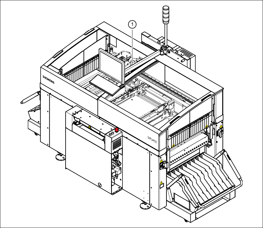
3.8.1 Position of the gantry
3
Fig. 3.8 - 1 Position of the gantry
3
(1) Gantry 1
The gantry system consists of two functional groups
– X axis and
–Y axis
3 Technical data User Manual SIPLACE CF
3.8 Gantry Software version SR.101.xx 06/2003 US Edition
88
3.8.2 Structure of the X axis
3
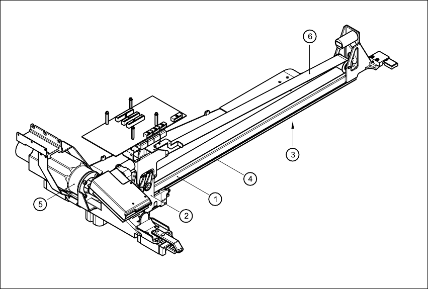
Fig. 3.8 - 2 Structure of the X axis
3
The X axis essentially consists of the following main modules:
– Gantry arm (1)
– Head mount (2)
– X axis measuring system (3)
– X axis guide system (4)
– X axis three-phase AC servomotor (5)
– Toothed belt (6)
The head mount holds the following components
– sub-gantry camera (camera for the PCB vision module)
– head board
– measuring head for the X axis measuring system
– Collect&Place head / Pick&Place head

User Manual SIPLACE CF 3 Technical data
Software version SR.101.xx 06/2003 US Edition 3.8 Gantry
89
3.8.3 Technical data for the X axis
3
3.8.4 Structure of the Y axis
The Y axis essentially consists of the following main modules:
– Y axis three-phase AC servomotor
– Y axis toothed belt
– Y axis guide system
– Y axis measuring system
The Y axis is driven by a three-phase AC servomotor. An anti-crash circuit limits the gantry tra-
versing path.
3.8.5 Technical data for the Y axis
3
Drive Three-phase AC servomotor/toothed belt
Maximum speed 2.5 m/sec.
Traversing path 620 mm
Distance measuring system Metal linear scale
Scale length 646 mm
Resolution 1.0 µm
Drive Three-phase AC servomotor/toothed belt
Maximum speed 2.5 m/sec.
Traversing path 910 mm
Distance measuring system Metal linear scale
Scale length 970 mm
Resolution 1.0 µm