Specification SIPLACE X-Series S 规格说明书.pdf - 第14页
14 Placement heads General Head modularity The SIPLACE placement machines are disting uished by maximum flexibility in the production proce ss. This flexibility is in part due to the head modularity of the place - ment m…

13
Machine performance
Placement head types SIPLACE SpeedStar (C&P20 P2)
SIPLACE MultiStar (CPP)
SIPLACE TwinStar (TH)
SIPLACE X4 S
Placement performance
For a definition of placement performance values, see the note on page 12.
Machine Placement area 1 Placement area 2 IPC value Benchmark
value
X4 S-A C&P20 P2 / C&P20 P2 C&P20 P2 / C&P20 P2 130,000 150,000
C&P20 P2 / C&P20 P2 CPP_L/CPP_L 102,400 119,000
C&P20 P2 / C&P20 P2 CPP_H / CPP_H 98,500 114,000
CPP_L/CPP_L CPP_L/CPP_L 74,800 88,000
CPP_L/CPP_L CPP_H / CPP_H 70,900 83,000
CPP_H / CPP_H CPP_H / CPP_H 67,000 78,000
X4 S-B C&P20 P2 / C&P20 P2 CPP_H/TH 86,250 99,500
CPP_L/CPP_L CPP_H/TH 58,650 68,500
CPP_H / CPP_H CPP_H/TH 54,750 63,500
X4 S-C C&P20 P2 / C&P20 P2 TH / TH 74,000 84,000
CPP_L/CPP_L TH / TH 46,500 53,000
CPP_H / CPP_H TH / TH 42,500 48,000
X4 S-D CPP_H/TH TH / TH 28,750 33,000
X4 S-E TH / TH TH / TH 16,000 18,000
SIPLACE X4i S
For a definition of placement performance values, see the note on page 12.
Machine Placement area 1 Placement area 2 IPC value Benchmark
value
X4i S-A C&P20 P2 / C&P20 P2 C&P20 P2 / C&P20 P2 146,000 172,000
C&P20 P2 / C&P20 P2 CPP_L/CPP_L 112,950 133,000
C&P20 P2 / C&P20 P2 CPP_H / CPP_H 107,000 126,000
CPP_L/CPP_L CPP_L/CPP_L 79,900 94,000
CPP_L/CPP_L CPP_H / CPP_H 73,950 87,000
CPP_H / CPP_H CPP_H / CPP_H 68,000 80,000
X4i S-B C&P20 P2 / C&P20 P2 CPP_H/TH 93,675 111,750
CPP_L/CPP_L CPP_H/TH 61,625 72,500
CPP_H / CPP_H CPP_H/TH 55,675 65,500
X4i S-C C&P20 P2 / C&P20 P2 TH / TH 81,350 97,250
CPP_L/CPP_L TH / TH 49,300 58,000
CPP_H / CPP_H TH / TH 43,350 51,000
CPP_H = Multistar CPP in high assembly position
CPP_L = Multistar CPP in low assembly position
14
Placement heads
General
Head modularity
The SIPLACE placement
machines are distinguished
by maximum flexibility in the
production process. This
flexibility is in part due to the
head modularity of the place-
ment machines, which allows
different placement head
variants to be configured to
suit the production require-
ments.
The SIPLACE SpeedStar
and the SIPLACE MultiStar
operate according to the
Collect&Place principle i.e.
one cycle includes pickup or
"collection" of 20 or 12 com-
ponents, their optical center-
ing on the board and their
rotation into the required
placement angle and posi-
tion. They are then placed
gently and accurately onto
the PCB. This principle is
particularly suitable for high-
speed placement of standard
components.
The SIPLACE MultiStar also
functions according to the
Pick&Place principle. Two
components are picked up
by the SIPLACE MultiStar,
optically centered on the way
to the placement position
and rotated into the required
placement angle. This princi-
ple is particularly suitable for
fast and precise placement
of large components.
The SIPLACE MultiStar uses
both the Collect&Place and
the Pick&Place principle.
Mixed Mode allows com-
bined use of these two
modes, which were previ-
ously separated from one
another, in one placement
cycle.
Pick&Place mode (Twin
Head)
The high-precision SIPLACE
TwinStar functions according
to the Pick&Place principle.
Two components are picked
up by the SIPLACE TwinStar
placement head, optically
centered on the way to the
placement position and then
rotated into the required
placement angle. This princi-
ple is particularly suitable for
fast and precise placement
of special components, such
as those required for grip-
pers etc.
Control and self-learning
functions
The reliability of the
SIPLACE placement heads
can be enhanced even fur-
ther with various checking
and self-learning functions.
• Component sensor
Checks the presence of
the components on the
nozzle before the pickup
and placement process
• Digital camera
Checks the position of
each component on the
nozzle. This check is per-
formed in a single step,
with no extra time involved
but with optimum scan-
ning of each individual
component.
• Force sensor
Monitors the prescribed
component set-down
force. The sensor stop
procedure enables com-
pensation of height differ-
ences during pickup and
PCB warpage during
placement.
• Vacuum sensor
Checks whether the com-
ponent was correctly
picked up or placed.
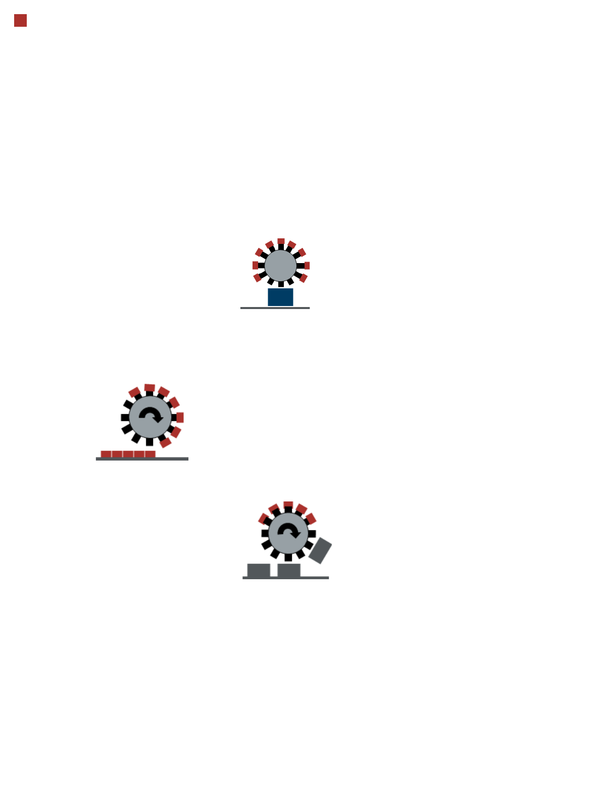
Collect&Place mode
Pick&Place mode
(SIPLACE MultiStar)
Mixed mode
15
Placement heads
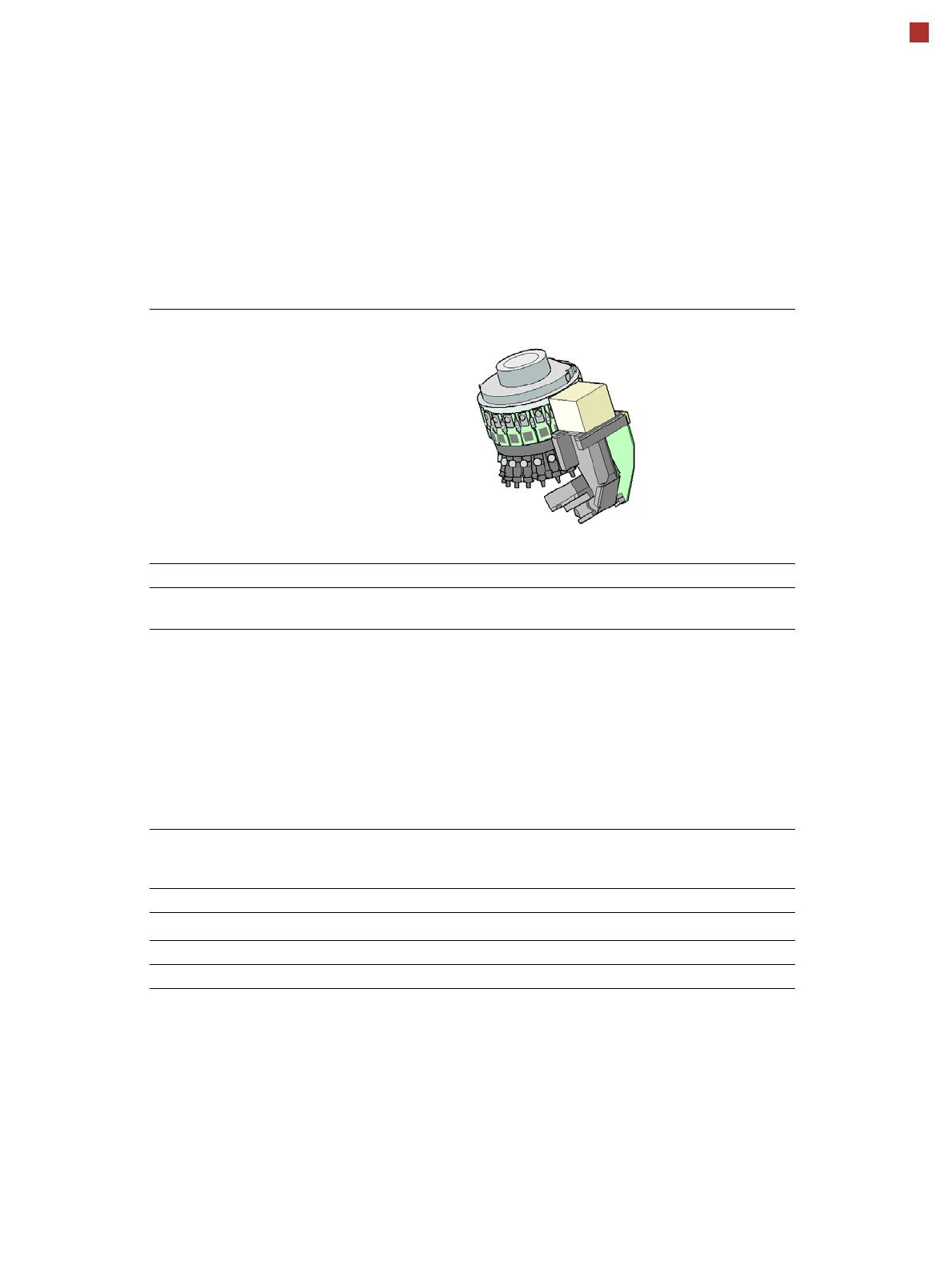
SIPLACE SpeedStar (C&P20 P2)
SIPLACE SpeedStar(C&P20 P2)
With component camera type 48
Component range
a
a) Please note that the placeable component range is also affected by the pad geometry, the customer-
specific standards, the component packaging tolerances and the component tolerances.
0.12 mm x 0.12 (0201 metric) to 2220, Melf, SOT, SOD, Bare-
Die, Flip-Chip
Component spec.
Max. height
Min. lead pitch
Min. lead width
Min. ball pitch
Min. ball diameter
Min. dimensions
Max. dimensions
Max. weight
4 mm
70 µm
30 µm
100 µm
50 µm
0.12 mm x 0.12 mm
8.2 mm x 8.2 mm
1 g
Set-down force 1.3 N ± 0.5N (default value)
0.5 N - 4.5 N
Touchless Placement
Nozzle types 60xx
X/Y accuracy
b
b) The accuracy values fulfill the conditions in the SIPLACE scope of supply and services.
± 34 µm/3σ
Angular accuracy ± 0.5° / 3σ
Illumination levels 5