Specification SIPLACE X-Series S 规格说明书.pdf - 第26页
26 Smart Pin Support Smart Pin Support The Smart Pin Support option automatically places support pins o n the lifting table. A gripper u nit is used to take the support pins out of the Smart Pin magazine and place them i…
25
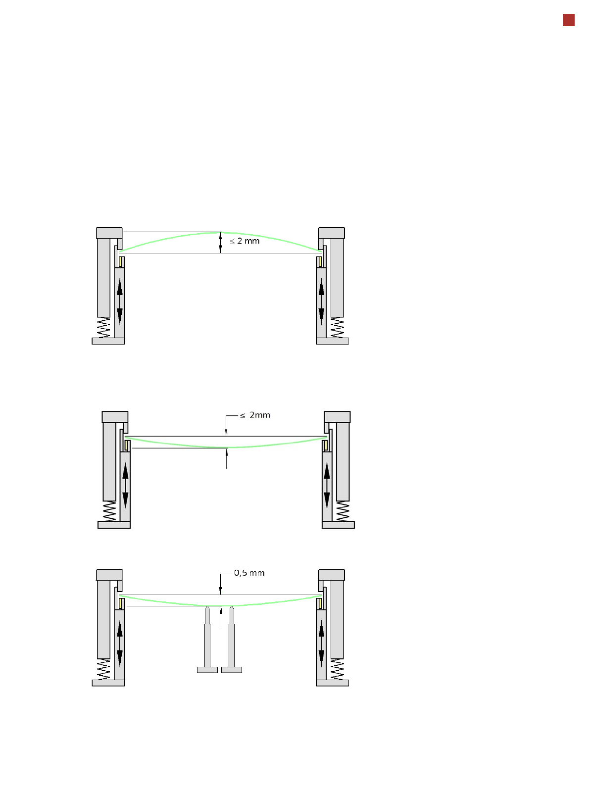
PCB warpage
PCB warpage during placement
To avoid impairing the placement quality and
speed, we recommend using a PCB support e.g.
Smart Pin Support so that the PCB warpage
downwards does not exceed 0.5 mm.
PCB warpage up, max. 2 mm
PCB support
PCB warpage down, max. 2 mm
Changes in the surface position are automatically applied by the functions for learning the height.
26
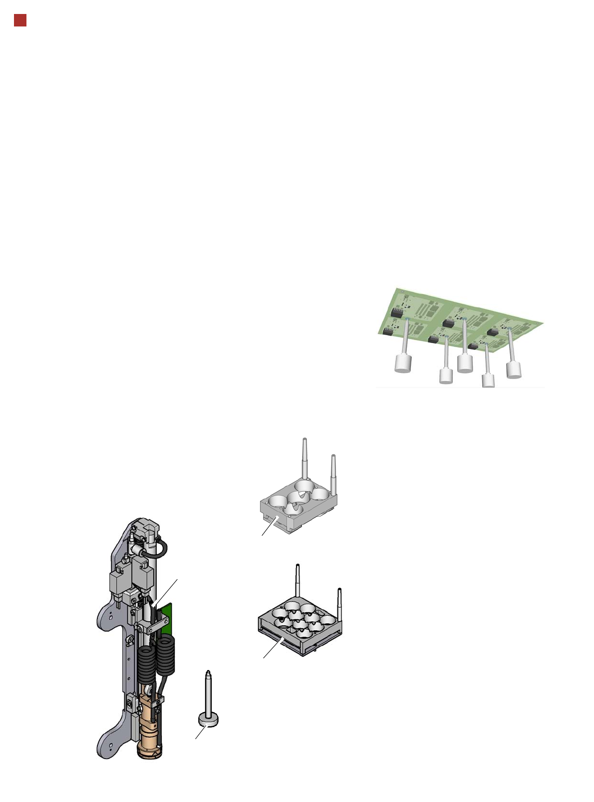
Smart Pin Support
Smart Pin Support
The Smart Pin Support
option automatically places
support pins on the lifting
table. A gripper unit is used
to take the support pins out of
the Smart Pin magazine
and place them in the pre-
defined positions.
Before placing the smart
support pin, the placement
area is cleaned of any impu-
rities with a gentle blast of air.
In addition, the correct posi-
tioning of the support pin is
checked after its placement,
with the PCB camera.
Smart Pin magazine
There are two different mag-
azines available for auto-
matic changeover of max. 5
or ma x. 10 su ppor t pins in the
various machine configura-
tions.
These magazines are fixed
to a magazine holder and are
fitted to the COT insert.
Programming
The positions of the support
pins in the placement
machine can be defined for
each board side, in the
SIPLACE Pro Board Editor.
A 3D image of the board and
the support pins enable you
to recognize and avoid any
potential collisions between
support pins and compo-
nents, even for stepped
transportation of very long
boards.
Support pin
Gripper unit
Magazine W5
Magazine Q 10
27
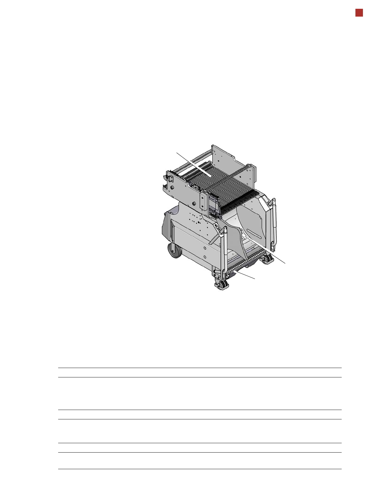
Component feeding
Component trolley X
Component trolley X
The SIPLACE X component
trolleys are independent and
easily maneuverable mod-
ules. Four component trol-
leys, each with 40 tracks, can
be docked onto SIPLACE X
machines. The tape reels are
taken up into the tape con-
tainer of the component trol-
ley. A cutting device on the
machine automatically cuts
up the used tape material.
The component trolleys can
be set up directly on the
machine or at an external
setup area with feeder mod-
ules. The benefits of offline
setup are that the configura-
tions can be prepared with-
out stopping the line.
This allows the setup change
to be realized very quickly,
using the changeover table
principle, to rapidly change
the component trolleys.
The SIPLACE X component
trolleys also support fast set-
ting up and tearing down of
feeder modules even during
the placement process.
Tapes can be spliced without
stopping the machine.
For safety reasons, unoccu-
pied locations are fitted with
so-called dummy feeder
modules.
Component trolley X
Tape container
Waste container for remaining empty
tape
Changeover table
Component supply Tracks occupied
4 component trolleys X on the SIPLACE X2 S / X3 S / X4 S
4 component trolleys X on the SIPLACE X4i S:
160 feeder modules, each with
8 mm X
148 feeder modules, each with
8 mm X
Tape reel diameter
Standard
Maximum
To 432 mm (17")
483 mm (19“)
Component trolley changeover time < 1 minute
Alternative feeder modules with adapter X Tape feeder modules, reject conveyor,
stick magazine and label presenter.