Specification SIPLACE X-Series S 规格说明书.pdf - 第23页
23 Board conveyor I-Placement Alternating placement mode Alternating placement or I-Placement mode Distance of outer conveyor edges: 680 mm, 2 lanes, outer conveyor edges fixed Alternating placement mode Distance of oute…

22
Board conveyor
Placement modes
Synchronous mode
In synchronous mode, two
boards are transported into
the placement position at the
same time. They are pro-
cessed as a common panel.
When using products with
greatly differing placement
content, common optimiza-
tion increases the perfor-
mance of the whole content
on both boards.
Asynchronous mode
In asynchronous mode, only
one board is processed on
one of the conveyor lanes. At
the same time, another
board on the second con-
veyor lane is moved into the
placement position. This
saves the full conveying time
of one board, thus consider-
ably increasing performance,
particularly for boards with a
short cycle time.
I-Placement
The SIPLACE line achieves
top placement performance
with the use of I-Placement.
In this mode, the two heads
work simultaneously and
populate the PCB on the cor-
responding conveyor side,
totally independently of one
another. Short distances fur-
ther increase the output.
Borrow Performance.
By facilitating simultaneous
production of two boards with
different contents in one line,
Borrow Performance is the
ideal addition to I-Placement.
In placement machines with
Borrow Performance, both
heads place the same board
in alternation The board in
the other conveyor lane is
simply transported through
the system. This makes it
possible to achieve the same
cycle time for both boards,
despite the different place-
ment contents.
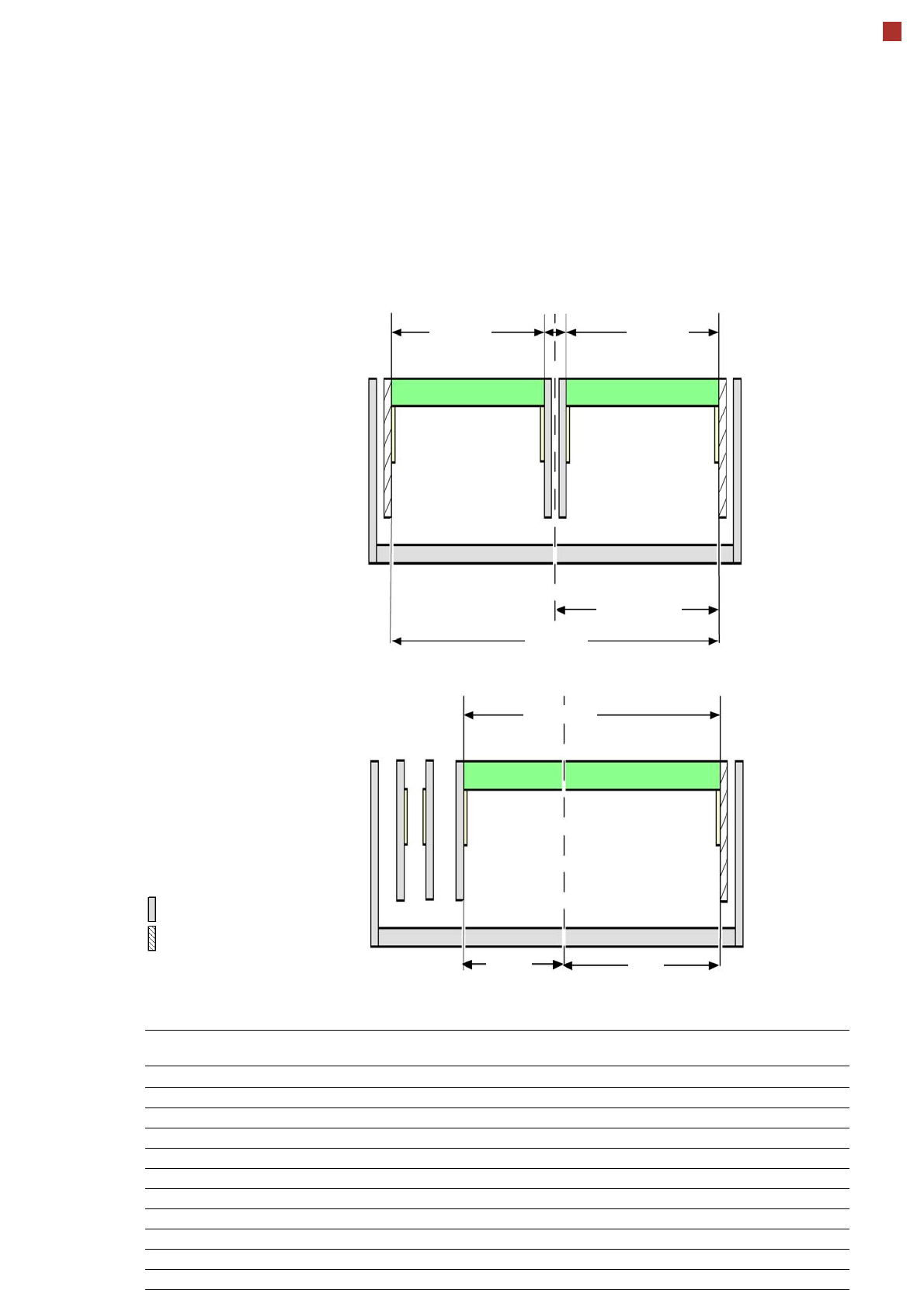
23
Board conveyor
I-Placement
Alternating placement mode
Alternating placement or
I-Placement mode
Distance of outer conveyor
edges: 680 mm, 2 lanes, outer
conveyor edges fixed
Alternating placement mode
Distance of outer conveyor
edges: 601 mm, dual conveyor
in single conveyor mode, right
conveyor edge fixed
a
max. 320
Movable conveyor side
Stationary conveyor side
a) The diagram only shows settings with a fixed righthand conveyor edge. A setting with the stationary conveyor
edge on the left is also possible. All dimensions in millimeters.
max. 320
344
680 (27“)
Min. 35
-344
+258
max. 601
Adjustable conveyor side position and max. PCB width
Conveyor side position Max. PCB width Distance of fixed sides to one another, for various fixed side
position settings
Outside Right or left
234.2 mm 216 mm 468.4 mm 2517 mm
254 mm 236 mm 508 mm 272 mm
259.7 mm 242 mm 519.4 mm 277.2 mm
268 mm 250 mm 536 mm 286 mm
268 mm SMEMA 250 mm 536 mm 285.5 mm
281 mm 260 mm 562 mm 299 mm
281 mm SMEMA 260 mm 562 mm 298.5 mm
320 mm 300 mm 640 mm 337.5 mm
344 mm 320 mm 688 mm 362 mm
Customized Max. 320 mm Max. 688 mm Max. 362 mm
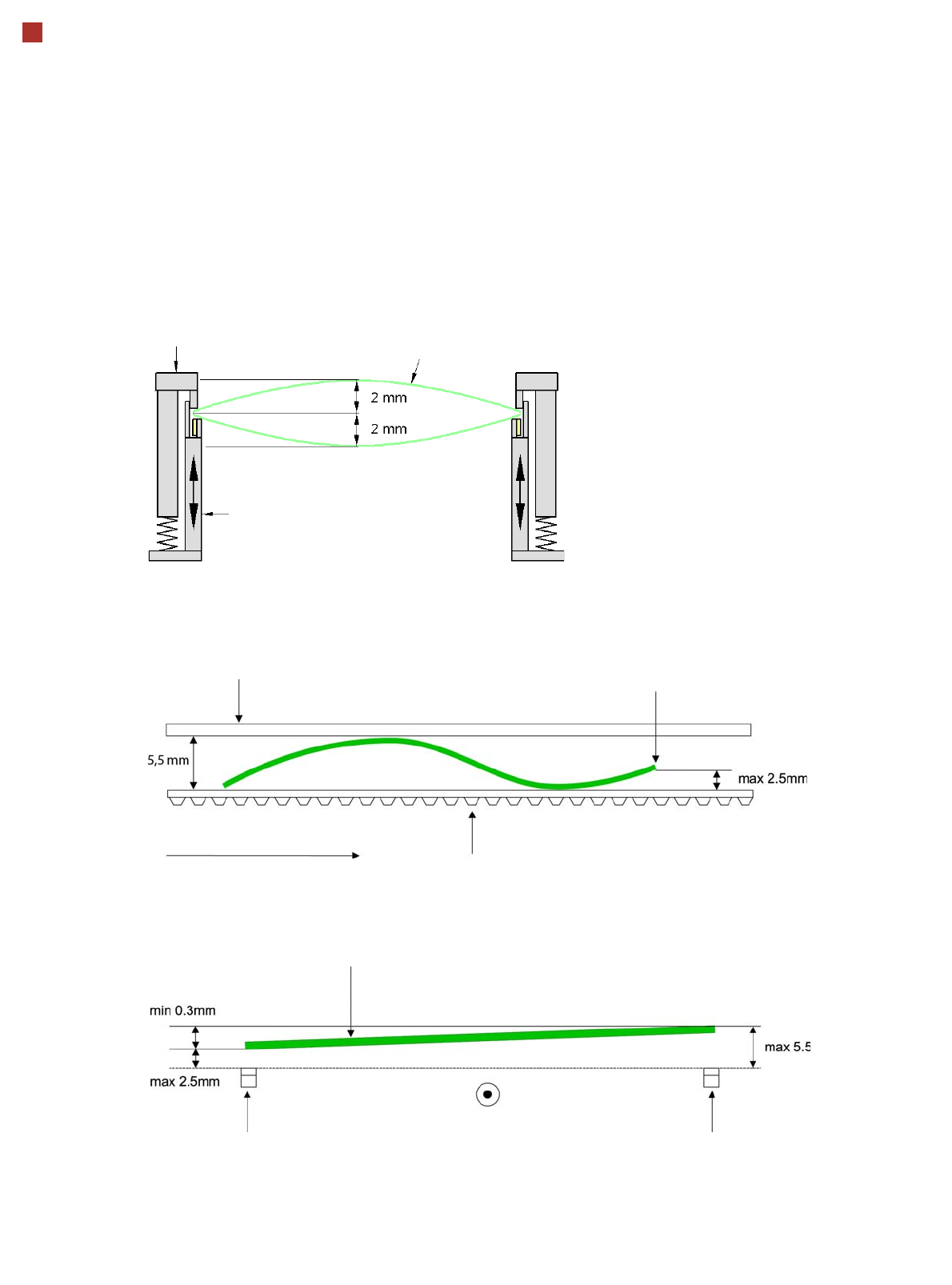
24
PCB warpage
PCB warpage across the direction of travel
max. 1% of the PCB diagonal, but not
exceeding 2 mm
PCB warpage on the conveyor
Fixed clamped edge
Movable clamping device
PCB
Fixed clamped edge
Conveyor belt
PCB transport direction
Front board edge
Front board edge
PCB warpage in direction of travel + PCB thickness < 5.5 mm
Bending up of front board edge max. 2.5 mm
Left conveyor belt
Right conveyor belt
PCB transport direction