Specification SIPLACE X-Series S 规格说明书.pdf - 第43页
43 OSC package The licensed OSC pack age contains functions for simpli- fied placement of odd shaped com ponents (O SC), such as connectors or sock- ets. The license is activate d via SIPLACE PRO. For detailed informatio…

42
SIPLACE Vision
Barcode types
Technical data
1D barcodes
QR codes
Code types Code 39
Code 93
Code 128
EAN-8 (AddOn 2, AddOn 5), EAN-13 (AddOn 2, AddOn 5)
Interleaved 2 of 5 (station software version 709.1 or higher required)
Minimum width of bar 5 pixels.
If the quality of the mark is sufficient, the width can be reduced down to 3
pixels.
Minimum height of symbol 5% of length of whole symbol.
Symbol angle All symbol angles will be accepted.
Inverse symbols Light bars on a dark background will be accepted.
(Station software version 708.0 or higher required)
Mirrored symbols Mirrored symbols will be accepted.
(this corresponds to a rotation of 180 degrees for 1D codes)
Region of Interest (ROI) The area on the board, in which the barcode is searched for (ROI), should
not exceed the following values:
ROI (direction of reading)
≤ 3 * symbol width
ROI (vertical to direction of reading) ≤ 10 * symbol width
Code type QR code in accordance with ISO/IEC 18004 model 2.
Station software version 711.0 or higher required
No. rows/columns All versions still defined in the standard (i.e. number of rows/columns) are
accepted.
Minimum dot size 5 pixels.
Symbol angle All symbol angles will be accepted.
Inverse symbols Inverse symbols (light modules on a dark background) will be accepted.
Mirrored symbols Mirrored symbols will be accepted.
Ratio of column width to row
height
1/2
≤ (column width) / (row height) ≤ 2
Region of Interest (ROI) The area in which the barcode is searched for (ROI) should not exceed the
following values:
Width of ROI
≤ 6 * width of barcode symbol
Height of ROI ≤ 6 * Height of barcode symbol
43
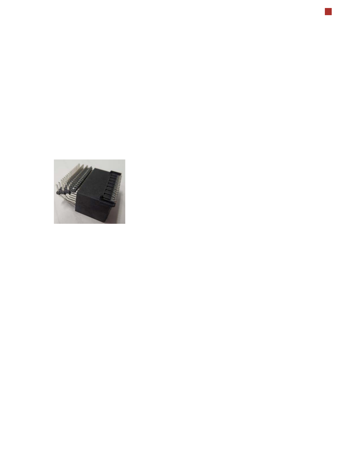
OSC package
The licensed OSC package
contains functions for simpli-
fied placement of odd
shaped components (OSC),
such as connectors or sock-
ets.
The license is activated via
SIPLACE PRO.
For detailed information,
refer to the OSC package
user guide, item number
[00198374-xx].
The following functions are
contained in the OSC pack-
age:
OSC measurement options
• Customized odd shaped
component
This enables the user to
describe any abstract pat-
tern on a component e.g.
connection leads of a tri-
angular shape. This pat-
tern can then be easily
created and edited at the
station, using the wizard
function.
• Stereo measurement
Stereo measurement
means that two images
are taken of each compo-
nent, from different direc-
tions, using a stationary
camera. These images
are overlapped to show
connectors, pins etc. in 3D
to support easy and pre-
cise evaluation of struc-
tures which, due to color,
shading or background
structures, are difficult to
recognize in conventional
2D measurement.
• Special position evalua-
tion
This function supports
separate definition of posi-
tion-determining features
(x,y, angle) independent
of the features for good-
bad recognition.
Placement of snap-in com-
ponents
This function monitors
whether snap-in components
engage in the board prop-
erly, during automatic place-
ment.
Pin in paste height check
This option extends the
"snap-in" function for CPP
and Twin heads.
Automatic calculation of
optimum acceleration
This function enables the
user to automatically calcu-
late the optimum accelera-
tion of individual axes for a
component at the station.
The acceleration values
found can then be checked in
an additional test run and
sent back to the program-
ming system if successful.
Placement of very high
components
In special application cases
the software can place a very
high component with auto-
matic collision prevention.
Additional force levels for
TH and CPP head
•30 N for TH
• 15 N for CPP
15.5 mm high components with CPP restrictions
• The maximum height of 15.5 mm can only be reached if the
PCB warpage upwards is 0 mm (setting in SIPLACE Pro).
• NO SIPLACE TwinStar permitted anywhere in the line.
• If there are two SIPLACE MultiStars (CPP) in the same
placement area, only one CPP can place components up to
15.5 mm.
44
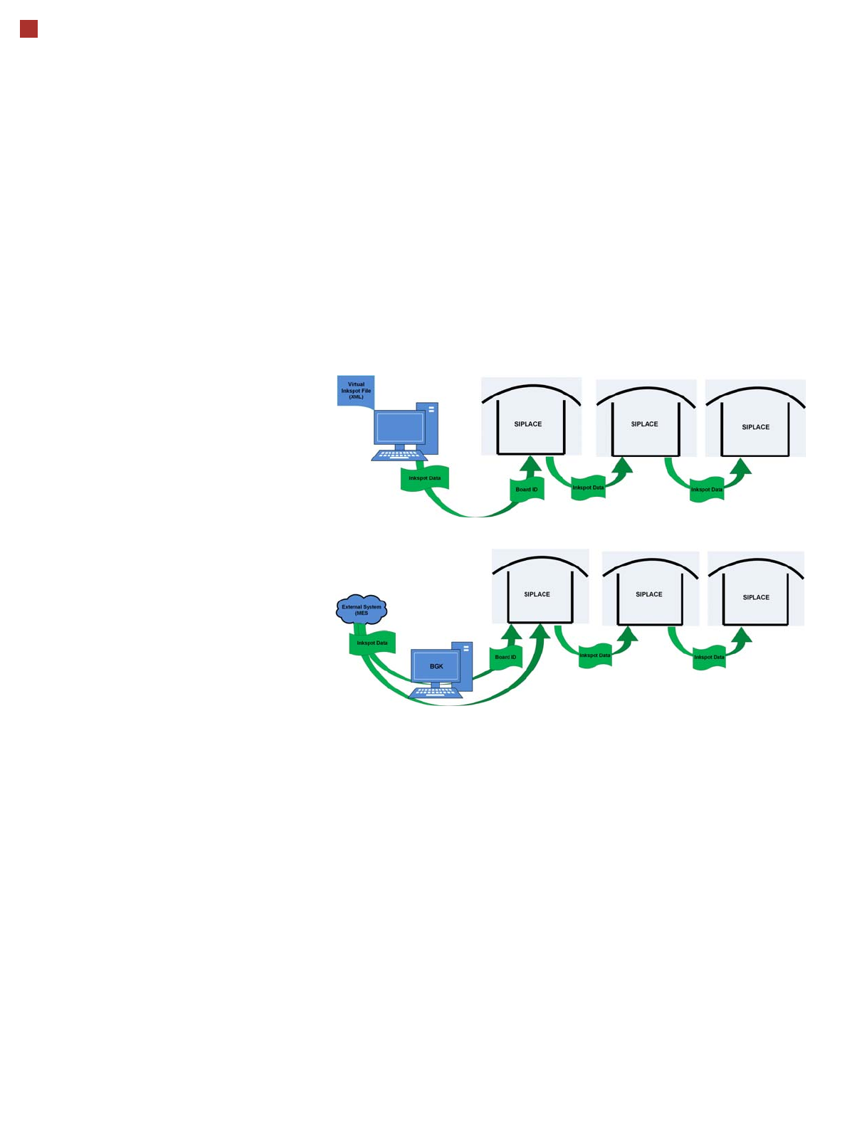
Virtual Inkspot Handler (VIH)
The virtual inkspot handler
(VIH) allows you to scan in
inkspots from an external
system.
This option can be used for
external systems to define
which panels are to be
produced and which to be
omitted. A panel is a specific
part of a printed circuit
board. This concept is much
more flexible than the
physical inkspot concept.
It can be integrated into the
ongoing production process,
if external systems
individually decide whether
each panel it is in a good or
bad state and whether
additional processing steps
are to be omitted or not.
The boards are typically
measured by the external
system and the information
about which panels are good
or bad is then available.
The use of this information
via VIH offers the benefit that
no physical inkspots need to
be read by the PCB camera.
This improves performance,
particularly for boards with a
large number of panels.
This option can also be used
if the panels do not have
room for a physical inkspot.
Workflow VIH with XML file
Workflow VIH with MES and BoardGateKeeper (BGK)
Process Data Interfaces (PDI)
The process data interface (PDI), which can be addressed via
the OIB interface, enables you to access not only the trace-
ability data of the components placed but also various process
parameters for the component placement. The PDI makes
over 40 process attributes per placement position available,
such as:
• Pickup (actual pick position, pickup location ID)
• Dipping (result, timestamp)
• Vision measuring (result plus camera ID)
• Placement (actual place position, ref. desig., vacuum val-
ues)
The data packages contain the data for each board and stop-
per position.
Each individual data package contains a maximum of 200
placement positions.