6-2-2-p0723-0782-cxsj_en.pdf - 第11页
Horizontal Mounting ø 10 to ø 32 ø 32 ø 25 ø 20 ø 15 ø 10 ø 10 ø 15 ø 20 ø 25 ø 32 Load mass m (kg) Load mass m (kg) Overhang L (mm) Overhang L (mm) 0 0.01 1 0.1 2 20 40 60 80 100 0 2 0.01 0.1 1 20 40 60 80 100 ø 32 ø 25…
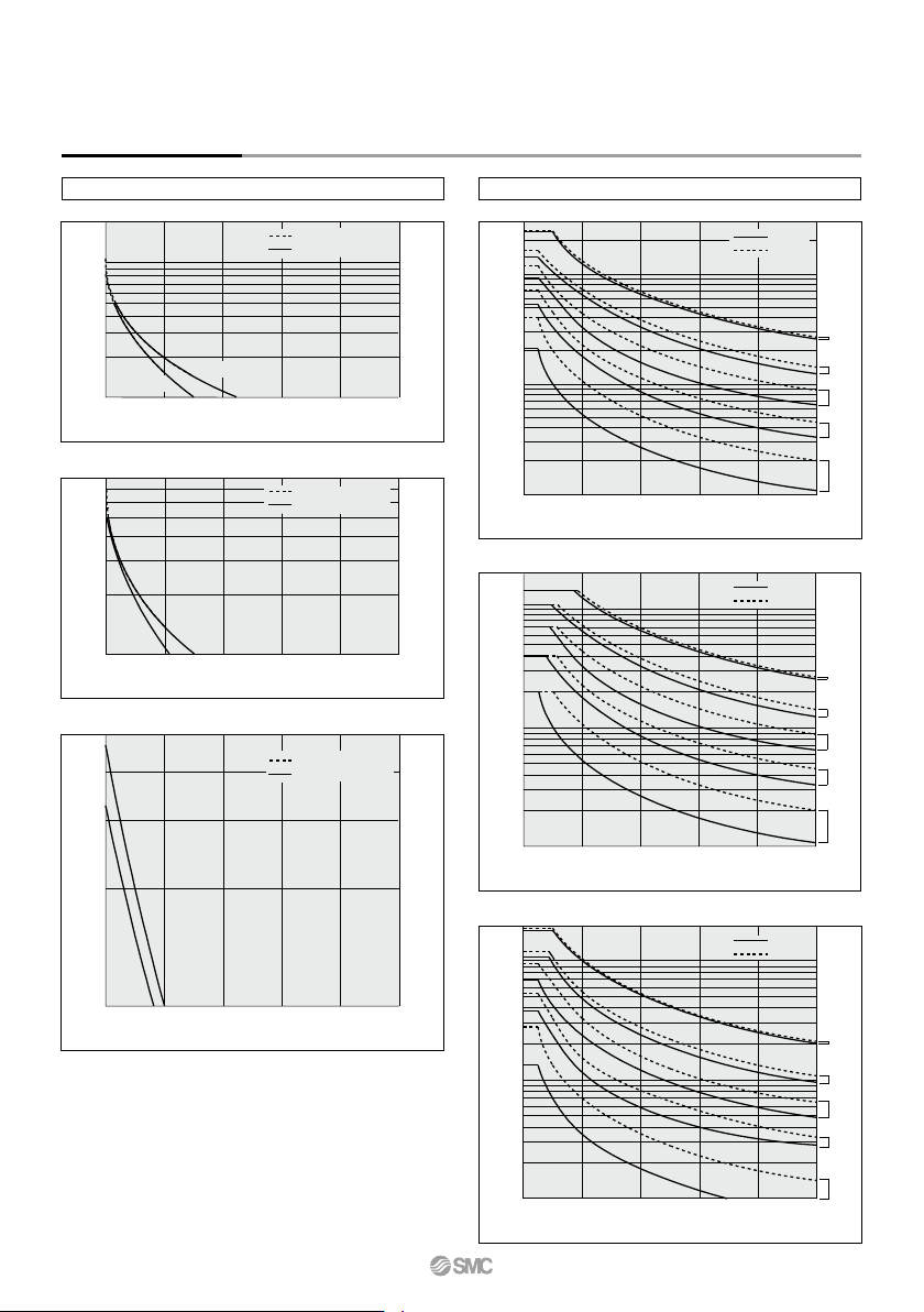
Horizontal Mounting
ø6 ø10 to ø32
Overhang L (mm)
0
0.01
0.05
0.1
20 40 60 80 100
Load mass m (kg)
Overhang L (mm)
0
0.01
0.05
0.1
0.5
1
3
2
20 40 60 80 100
Load mass m (kg)
ø32
ø25
ø20
ø15
ø10
Graph (7) Up to 10 st
Graph (10) V = Up to 400 mm/s; Up to 10 st
V = Up to 100 mm/s
V = Up to 300 mm/s
Overhang L (mm)
0
0.01
0.02
0.03
0.04
0.05
20 40 60 80 100
CXSL6
CXSM6
Load mass m (kg)
Graph (9) Up to 50 st
V = Up to 100 mm/s
V = Up to 300 mm/s
0
0.01
0.05
20 40 60 80 100
CXSL6
CXSM6
Load mass m (kg)
Overhang L (mm)
Graph (8) Up to 30 st
V = Up to 100 mm/s
V = Up to 300 mm/s
CXSM
CXSL
0
0.01
0.05
0.1
0.5
1
2
20 40 60 80 100
Load mass m (kg)
Overhang L (mm)
ø32
ø25
ø20
ø15
ø10
Graph (11) V = Over 400 mm/s; Up to 10 st
CXSM
CXSL
Overhang L (mm)
0
0.01
0.05
1
2
0.1
20 40 60 80 100
Load mass m (kg)
ø32
ø25
ø20
ø15
ø10
Graph (12) V = Up to 400 mm/s; Up to 30 st
CXSM
CXSL
CXSM6
CXSL6
CXS Series
732
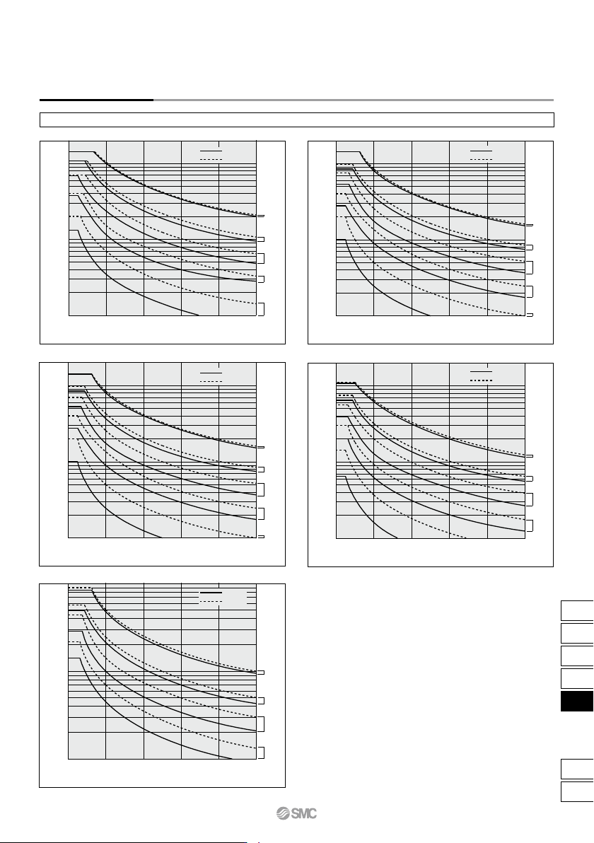
Horizontal Mounting
ø10 to ø32
ø32
ø25
ø20
ø15
ø10
ø10
ø15
ø20
ø25
ø32
Load mass m (kg)
Load mass m (kg)
Overhang L (mm)
Overhang L (mm)
0
0.01
1
0.1
2
20 40 60 80 100
0
2
0.01
0.1
1
20 40 60 80 100
ø32
ø25
ø20
ø15
ø10
ø15
ø20
ø25
ø32
Load mass m (kg)
Load mass m (kg)
Overhang L (mm)
Overhang L (mm)
0
0.01
0.05
0.1
0.5
1
2
20 40 60 80 100
0
1
0.01
0.1
20 40 60 80 100
0
0.01
0.05
0.1
0.5
1
2
20 40 60 80 100
Load mass m (kg)
Overhang L (mm)
ø32
ø25
ø20
ø15
ø10
Graph (13) V = Over 400 mm/s; Up to 30 st
CXSM
CXSL
Graph (14) V = Up to 400 mm/s; Up to 50 st
Graph (15) V = Over 400 mm/s; Up to 50 st
CXSM
CXSL
CXSM
CXSL
Graph (16) V = Over 400 mm/s; Up to 75 st
Graph (17) V = Over 400 mm/s; Up to 100 st
CXSM
CXSL
CXSM
CXSL
Model Selection/Basic Type CXS Series
733
CX2
CXW
CXT
CXSJ
CXS
D-
-X
CXS
Model Selection/With Air Cushion
CXS
Series
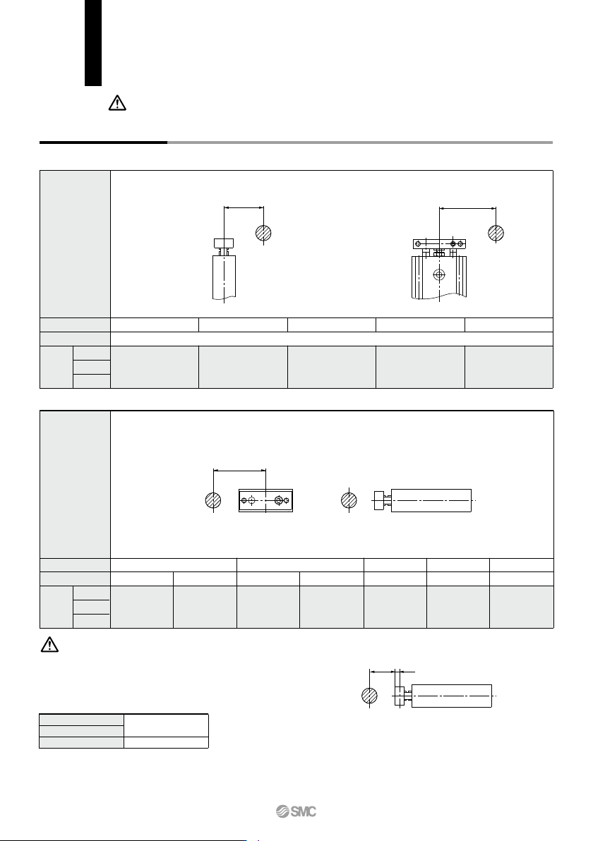
With Air Cushion: CXS
Caution Confirmation of theoretical output is required separately.
Refer to “Theoretical Output Table” on page 762.
Max. speed (mm/s)
Stroke (mm)
ø
25
ø20
ø32
Selection
graph
Mounting
orientation
Vertical Mounting
Up to 200
All strokes
(1) (2) (3) (4)
Up to 600 Up to 800
(5)
Up to 1000Up to 400
Imaginary stroke L' = (Stroke) + k + L
k: Distance between the center and the end of the plate
ø
20
ø25
ø32
6 mm
8 mm
Stroke (mm)
Max. speed (mm/s)
ø25
ø20
ø32
Selection
graph
Mounting
orientation
Horizontal Mounting
Up to 10 Up to 30
Up to 1000Up to 800 Up to 1000 Up to 1000Up to 800
Up to 50
(6) (7) (8) (9) (10)
Up to 1000
Up to 75
(11)
Up to 1000
Up to 100
(12)
L
m
L
m
m m
L
k
∗ Refer to the caution notes below.
If the cylinder is horizontally mounted and the plate end does not reach the load's center of
gravity, use the formula below to calculate the imaginary stroke L' that includes the distance
between the load's center of gravity and the plate end. Select the graph that corresponds to
the imaginary stroke L'.
(Example)
When using CXSM20-10 and L = 10 mm:
Imaginary stroke L' = 10 + 6 + 10 = 26
Therefore, the graph used for your model selection should be the one for CXSM20-30.
Caution
L
734