6-2-2-p0723-0782-cxsj_en.pdf - 第30页
Whe n opera ting an ac tuato r with a sm all dia m- eter an d a shor t stroke at a hi gh freq uenc y, the dew c onde nsat ion (wat er dro plet) may oc cur ins ide th e pipi ng de pend ing on t he con diti ons. Sim ply co…
Dual Rod Cylinder
Basic Type
CXS Series
ø6, ø10, ø15, ø20, ø25, ø32
CXS M Y7BW10020
M
L
15, 20
25, 32
10
Without auto switch (Built-in magnet)
Z76
Z73
Y59A
Y7P
Y59B
Y7NW
Y7PW
Y7BW
Y7BA
∗∗
Y69A
Y7PV
Y69B
Y7NWV
Y7PWV
Y7BWV
Z80
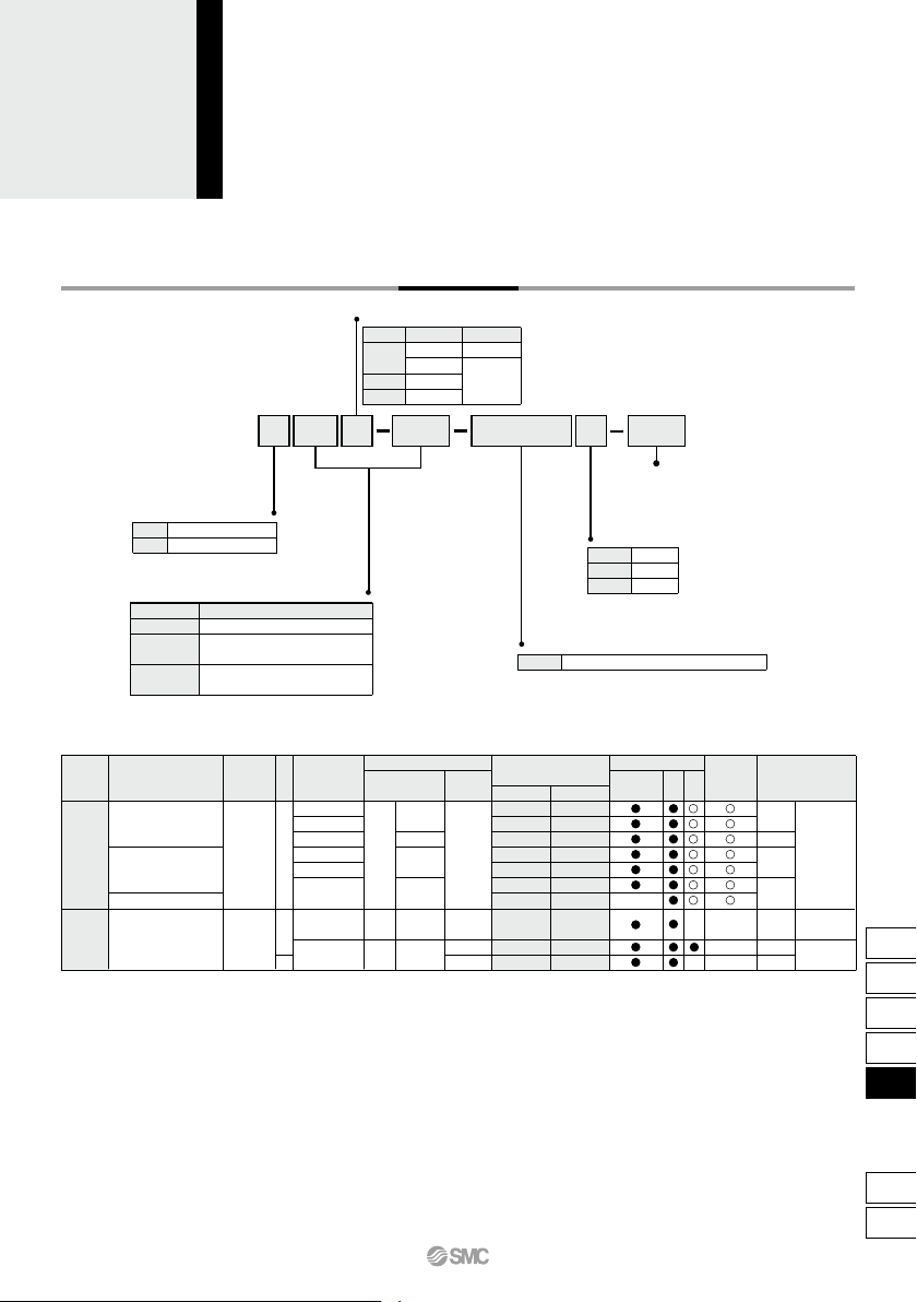
How to Order
Thread type
Symbol Bore size
ø6 to ø20
ø25,ø32
Type
M thread
Rc 1/8
NPT 1/8
G 1/8
Nil
TN
TF
Bearing type
Slide bearing
Ball bushing bearing
2 pcs.
1 pc.
“n” pcs.
Number of auto switches
Nil
S
n
Auto switch
Nil
∗ For the applicable auto switch model, refer to the table below.
Bore size
6
Standard stroke (mm)
10, 20, 30, 40, 50
10, 15, 20, 25, 30, 35, 40, 45,
50, 60, 70, 75
10, 15, 20, 25, 30, 35, 40, 45,
50, 60, 70, 75, 80, 90, 100
Bore size/Stroke (mm)
Applicable Auto Switches/Refer to pages 1119 to 1245 for further information on auto switches.
Made to Order
Refer to page 750 for details.
Special functionType
Electrical
entry
Indicator light
Wiring
(Output)
Water resistant
(2-color indicator)
Diagnostic indication
(2-color indicator)
Yes
None
Yes
Grommet
Grommet
3-wire (NPN)
3-wire (PNP)
2-wire
3-wire (NPN)
3-wire (PNP)
2-wire
2-wire
3-wire
(NPN equivalent)
Reed
auto switch
Solid state auto switch
—
—
AC
DC
24 V 12 V
5 V
5 V, 12 V
12 V
5 V, 12 V
12 V
24 V
100 V
100 V or less
Load voltage
Auto switch model
Perpendicular
In-line
—
—
—
—
—
—
—
Lead wire length (m)
∗
0.5
(Nil)
3
(L)
5
(Z)
—
—
—
—
—
—
IC
circuit
IC
circuit
IC
circuit
IC circuit
Applicable load
—
—
—
—
Pre-wired
connector
Relay,
PLC
Relay,
PLC
• Since there are other applicable auto switches than listed, refer to page 758 for details.
• For details about auto switches with pre-wired connector, refer to pages 1192 and 1193.
• Auto switches are shipped together (not assembled).
∗ Solid state auto switches marked with “” are produced upon receipt of order.
∗∗ Water resistant type auto switches can be mounted on the above models, but in such case SMC cannot guarantee water resistance.
Consult with SMC regarding water resistant types with the above model numbers.
∗ Lead wire length symbols: 0.5 m ·········· Nil (Example) Y59A
3 m ·········· L (Example) Y59AL
5 m ·········· Z (Example) Y59AZ
749
CX2
CXW
CXT
CXSJ
CXS
D-
-X
CXS
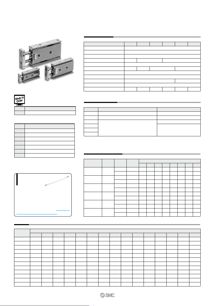
When operating an actuator with a small diam-
eter and a short stroke at a high frequency, the
dew condensation (water droplet) may occur
inside the piping depending on the conditions.
Simply connecting the moisture control tube to
the actuator will prevent dew condensation
from occurring. For details, refer to the IDK se-
ries in the Best Pneumatics No. 6.
Moisture
Control Tube
IDK Series
-X593
Without plate
Symbol
Specifications
Made to Order: Individual
Specifications
(For details, refer to page 759.)
Weight
Standard Stroke
CXSM 6
CXSL 6
CXSM10
CXSL 10
CXSM15
CXSL 15
CXSM20
CXSL 20
CXSM25
CXSL 25
CXSM32
CXSL 32
10
0.081
0.081
0.15
0.15
0.25
0.27
0.40
0.43
0.61
0.62
1.15
1.16
15
—
—
0.16
0.16
0.265
0.285
0.42
0.445
0.635
0.645
1.19
1.205
20
0.095
0.095
0.17
0.17
0.28
0.30
0.44
0.46
0.66
0.67
1.23
1.25
25
—
—
0.18
0.18
0.29
0.31
0.46
0.48
0.69
0.70
1.275
1.295
30
0.108
0.108
0.19
0.19
0.30
0.32
0.48
0.50
0.72
0.73
1.32
1.34
35
—
—
0.20
0.20
0.315
0.335
0.495
0.515
0.745
0.755
1.36
1.38
40
0.122
0.122
0.21
0.21
0.33
0.35
0.51
0.53
0.77
0.78
1.40
1.42
50
0.135
0.135
0.23
0.23
0.36
0.38
0.55
0.57
0.83
0.84
1.49
1.51
45
—
—
0.22
0.22
0.345
0.365
0.53
0.55
0.80
0.81
1.45
1.465
60
—
—
0.25
0.25
0.39
0.41
0.585
0.605
0.89
0.895
1.58
1.595
70
—
—
0.27
0.27
0.42
0.44
0.62
0.64
0.95
0.955
1.665
1.68
75
—
—
0.28
0.28
0.435
0.455
0.64
0.66
0.97
0.98
1.71
1.72
80
—
—
—
—
0.45
0.47
0.66
0.68
0.995
1.005
1.755
1.765
90
—
—
—
—
0.48
0.50
0.70
0.715
1.06
1.065
1.84
1.855
100
—
—
—
—
0.51
0.53
0.74
0.75
1.10
1.11
1.93
1.94
CXS6
CXS10
CXS15
CXS20
CXS25
CXS32
15
6 20 25 32
0.1
—
—
15.7
10.0
35.3
25.2
62.8
47.1
98.2
75.6
161
121
0.2
11.2
6.2
31.4
20.0
70.6
50.4
126
94.2
196
151
322
241
0.3
16.8
9.3
47.1
30.0
106
75.6
188
141
295
227
482
362
0.4
22.4
12.4
62.8
40.0
141
101
251
188
393
302
643
482
0.5
28.0
15.5
78.5
50.0
177
126
314
236
491
378
804
603
0.6
33.6
18.6
94.2
60.0
212
151
377
283
589
454
965
724
0.7
39.2
21.7
110
70.0
247
176
440
330
687
529
1126
844
0.15
8.4
4.6
—
—
—
—
—
—
—
—
—
—
56
31
157
100
353
252
628
471
982
756
1608
1206
OUT
IN
OUT
IN
OUT
IN
OUT
IN
OUT
IN
OUT
IN
4
6
8
10
12
16
CXS6
CXS10
CXS15
CXS20
CXS25
CXS32
60, 70, 75, 80, 90, 100
80, 90, 100, 110, 120, 125, 150
110, 120, 125, 150
110, 120, 125, 150, 175, 200
CXS Series
Specifications
0.095 J
0.0023 J 0.064 J 0.17 J 0.27 J 0.32 J
(mm)
(N)
Theoretical Output
Made to Order Specifications
Click here for details
(kg)
Bore size (mm)
Fluid
Proof pressure
Maximum operating pressure
Minimum operating pressure
Ambient and fluid temperature
Piston speed
Cushion
Stroke adjustable range
Port size
Bearing type
Allowable kinetic energy
Air (Non-lube)
1.05 MPa
0.7 MPa
–10 to 60°C (No freezing)
10
30 to 800 mm/s
Slide bearing, Ball bushing bearing (Same dimensions for both)
30 to 700 mm/s
Rubber bumper
0 to –5 mm compared to the standard stroke
30 to 600 mm/s
Rc 1/8
0.1 MPa 0.05 MPa
0.15 MPa
30 to 300 mm/s
M5 x 0.8
Model
Standard stroke
Long stroke
10, 15, 20, 25, 30, 35, 40, 45, 50,
60, 70, 75, 80, 90, 100
10, 20, 30, 40, 50
10, 15, 20, 25, 30, 35, 40, 45, 50, 60, 70, 75
∗ Refer to “Made to Order Specifications” for stroke which exceeds the standard stroke length.
Non-standard strokes for a size ø6 cylinder are available as a special order.
Operating pressure (MPa)
Operating
direction
Piston area
(mm
2
)
Rod size
(mm)
Model
Note) Theoretical output (N) = Pressure (MPa) x Piston area (mm
2
)
Model
Standard stroke (mm)
-XB6
-XB9
-XB11
-XB13
-XB19
-XC22
-XC85
Symbol
Specifications
Heat resistant cylinder (–10 to 150°C)
Low speed cylinder (10 to 50 mm/s)
Long stroke type
Low speed cylinder (5 to 50 mm/s)
High speed specification
Fluororubber seals
Grease for food processing equipment
750
B
CXSM
CXSL
ø6
ø32
ø25
ø20
ø15
ø10
CXS6 to 32
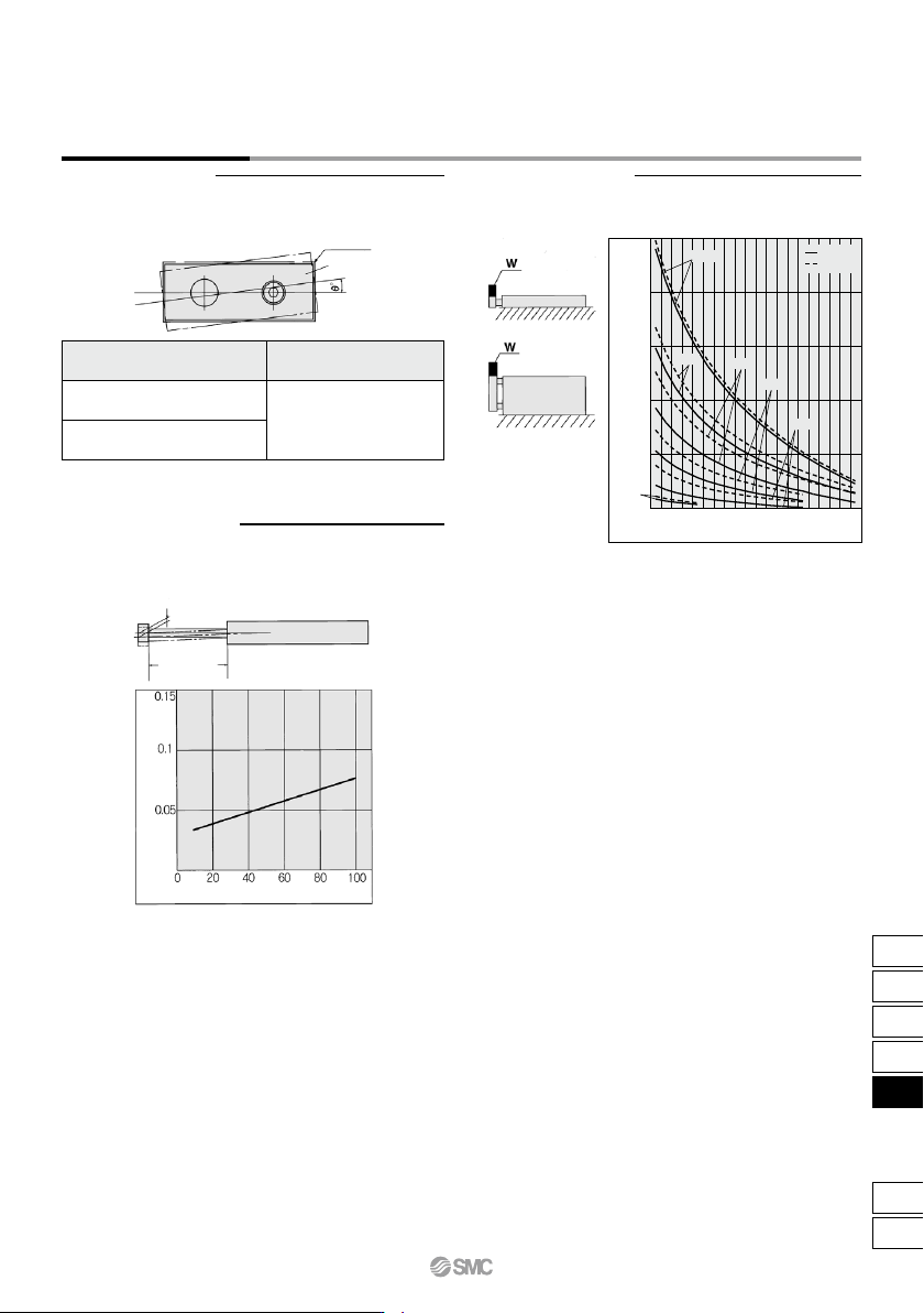
Deflection at the Plate End
Operating Conditions
Non-rotating Accuracy Maximum Load Mass
Cylinder stroke (mm)
Maximum load mass W (kg)
0.5
1
1.5
2
2.5
20 40 60 80 100 120 140 160 180 200
0
Non-rotating accuracy θ° at the retracted end and without a load should
be less than or equal to the value provided in the table below as a guide.
Housing
Plate
Bore size (mm)
ø6 to ø32
±0.1°
CXSM
(Slide bearing)
CXSL
(Ball bushing bearing)
An approximate plate-end deflection X without a load is shown in the
graph below.
Deflection
X mm
Extended
rod
Deflection X (mm)
Stroke (mm)
When the cylinder is mounted as shown in the diagrams below, the
maximum load mass W should not exceed the values illustrated in the
graph.
751
CXS Series
Dual Rod Cylinder
Basic Type
CX2
CXW
CXT
CXSJ
CXS
D-
-X
CXS