6-2-2-p0723-0782-cxsj_en.pdf - 第47页
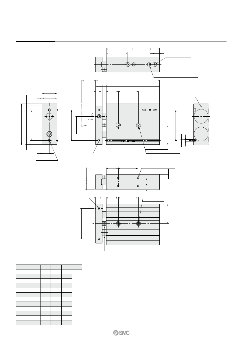
Note) Adjust the auto switch after confirming the operating conditions in the actual setting. 20 25 32 B A C 36.5(35) 38(36.5) 48.5(47) 40.5 42 52.5 6.5 8 9.5 D 2.5(1) 4(2.5) 5.5(4) C 38.5 40 50.5 D 4 5.5 7 C 30.5 32 42.…
S
25
30
35
40
45
50
60
70
75
80
90
100
SS
112
117
122
127
132
137
147
157
162
167
177
187
ZZ
142
147
152
157
162
167
177
187
192
197
207
217
Z
40
50
70
Z
SS
ZZS
(Z)
19 11.5
T
Dimensions: ø32
308
16 14
44
67.5 23.5
54
10
96
18
361
38
102
(5)
1
49
75 ±
0.2
75 ±
0.2
2 x M6 x 1.0
(Through-hole)
thread depth 8
2 x M5 x 0.8
2 x ø6.9 through
2 x ø11 counterbore depth 6.3
2 x Rc 1/8 thread depth 6.5 (Piping port)
Note)
2 x cushion needle
(Steel ball)
5
76
6.3
4 x M5 x 0.8 thread depth 7.5
30
9 20
CXS32-25A
CXS32-30A
CXS32-35A
CXS32-40A
CXS32-45A
CXS32-50A
CXS32-60A
CXS32-70A
CXS32-75A
CXS32-80A
CXS32-90A
CXS32-100A
Part no.
(mm)
Note) For port threads TN and TF, only the piping port type varies.
CXS Series
2 x M5 x 0.8 thread depth 8
2 x M8 x 1.25
thread depth 12
(30) (Z)8
75 ±
0.2
ø16
(49)
766
Note) Adjust the auto switch after confirming the operating conditions in the actual setting.
20
25
32
BA
C
36.5(35)
38(36.5)
48.5(47)
40.5
42
52.5
6.5
8
9.5
D
2.5(1)
4(2.5)
5.5(4)
C
38.5
40
50.5
D
4
5.5
7
C
30.5
32
42.5
D
–3.5
–2
–0.5
D
C
B
A
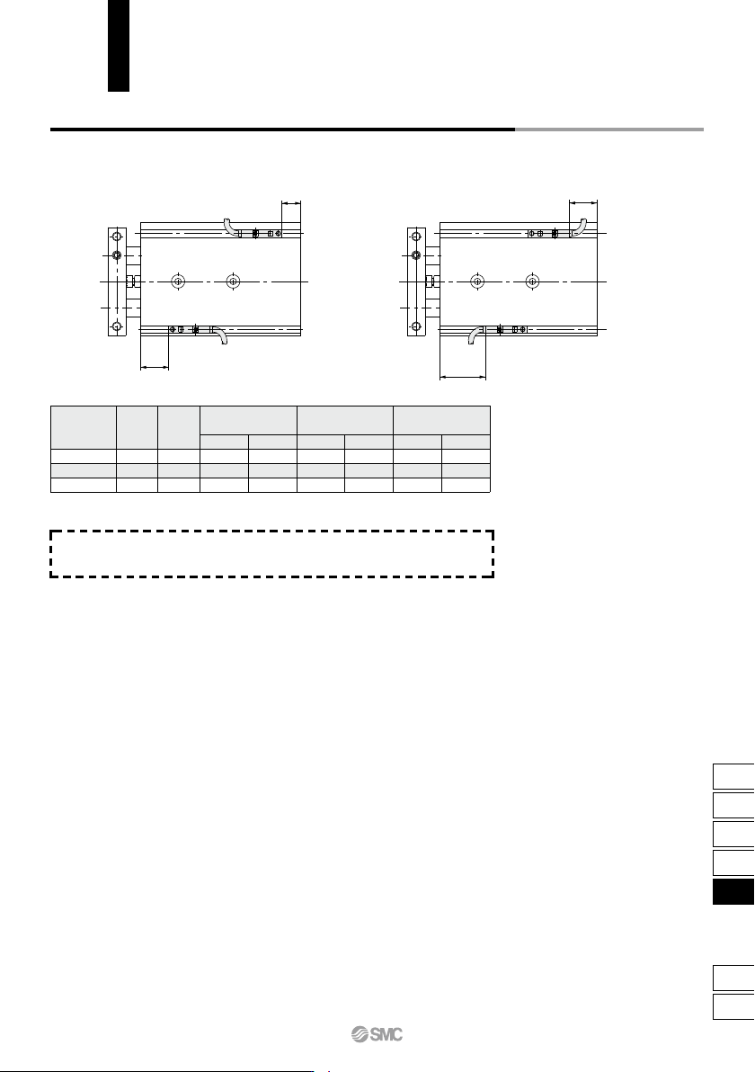
Auto Switch Proper Mounting Position (Detection at Stroke End)
Electrical entry direction: Inward Electrical entry direction: Outward
D-Z7/Z8, D-Y7W
D-Y5, D-Y7
D-Y6, D-Y7V
D-Y7WV
D-Y7BA
Bore size
(mm)
As for auto switch mounting dimensions, auto switch mounting method
and its operating range, those are the same as basic type. Refer to page
758.
CXS Series
Auto Switch Mounting
767
CX2
CXW
CXT
CXSJ
CXS
D-
-X
CXS
CXS M
Y7BW
50 R10
M
L
With end lock for retraction side
Z76
Z73
Y59A
Y7P
Y59B
Y7NW
Y7PW
Y7BW
Y7BA
∗∗
Y69A
Y7PV
Y69B
Y7NWV
Y7PWV
Y7BWV
Z73
Z80
Lead wire length (m)
∗
CXS Series
ø6, ø10, ø15, ø20, ø25, ø32
Wiring
(Output)
100 V or less
Load voltage
Pre-wired
connector
Applicable load
Dual Rod Cylinder
With End Lock for Retraction Side
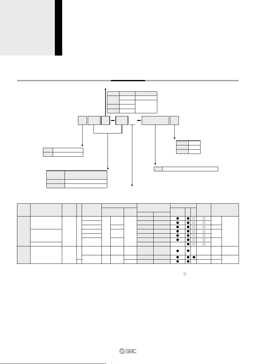
How to Order
Bearing type
Slide bearing
Ball bushing bearing
Bore size/Stroke (mm)
Bore size
(mm)
10, 20, 30, 40, 50
10, 20, 30, 40, 50, 75, 100
Stroke (mm)
6, 10, 15
20, 25, 32
Number of auto switches
2 pcs.
1 pc.
“n” pcs.
Nil
S
n
Auto switch
Nil
Without auto switch (Built-in magnet)
∗ For the applicable auto switch model, refer to the table below.
Applicable Auto Switches/Refer to pages 1119 to 1245 for further information on auto switches.
Special functionType
Electrical
entry
Indicator light
YesYes
Grommet
Grommet
Reed
auto switch
Solid state auto switch
—
—
Water resistant
(2-color indicator)
Diagnostic indication
(2-color indicator)
None
3-wire (NPN)
3-wire (PNP)
2-wire
3-wire (NPN)
3-wire (PNP)
2-wire
2-wire
3-wire
(NPN equivalent)
AC
DC
5 V
5 V, 12 V
12 V
5 V, 12 V
12 V
24 V
—
24 V 12 V
100 V
—
—
—
—
—
—
Auto switch model
Perpendicular
In-line
0.5
(Nil)
3
(L)
5
(Z)
—
—
—
—
—
—
IC
circuit
IC
circuit
IC
circuit
IC circuit
—
—
—
—
Relay,
PLC
Relay,
PLC
• Since there are other applicable auto switches than listed, refer to page 758 for details.
• For details about auto switches with pre-wired connector, refer to pages 1192 and 1193.
• Auto switches are shipped together (not assembled).
∗ Solid state auto switches marked with “ ” are produced upon receipt of order.
∗∗ Water resistant type auto switches can be mounted on the above models, but in such case SMC cannot guarantee water resistance.
Consult with SMC regarding water resistant types with the above model numbers.
∗ Lead wire length symbols: 0.5 m ·········· Nil (Example) Y59A
3 m ·········· L (Example) Y59AL
5 m ·········· Z (Example) Y59AZ
Thread type
Bore size
ø6 to ø20
ø25, ø32
Type
M thread
Rc 1/8
NPT 1/8
G 1/8
Symbol
Nil
TN
TF
768