6-2-2-p0723-0782-cxsj_en.pdf - 第39页
Without Plate 1 This specification is for the cylinder without a plate . This cylinder is suitable f or mounting your o wn plate. Please note that the rod end dimensions of this cylinder are different from those of the s…
A
B
A
C
D
6
0.7 0.2
1.2 0.7
10 15 20 25 32
∗ Normally closed (NC = b contact), solid state auto switch (D-Y7G/Y7H type) are also available. For details, refer to page 1139.
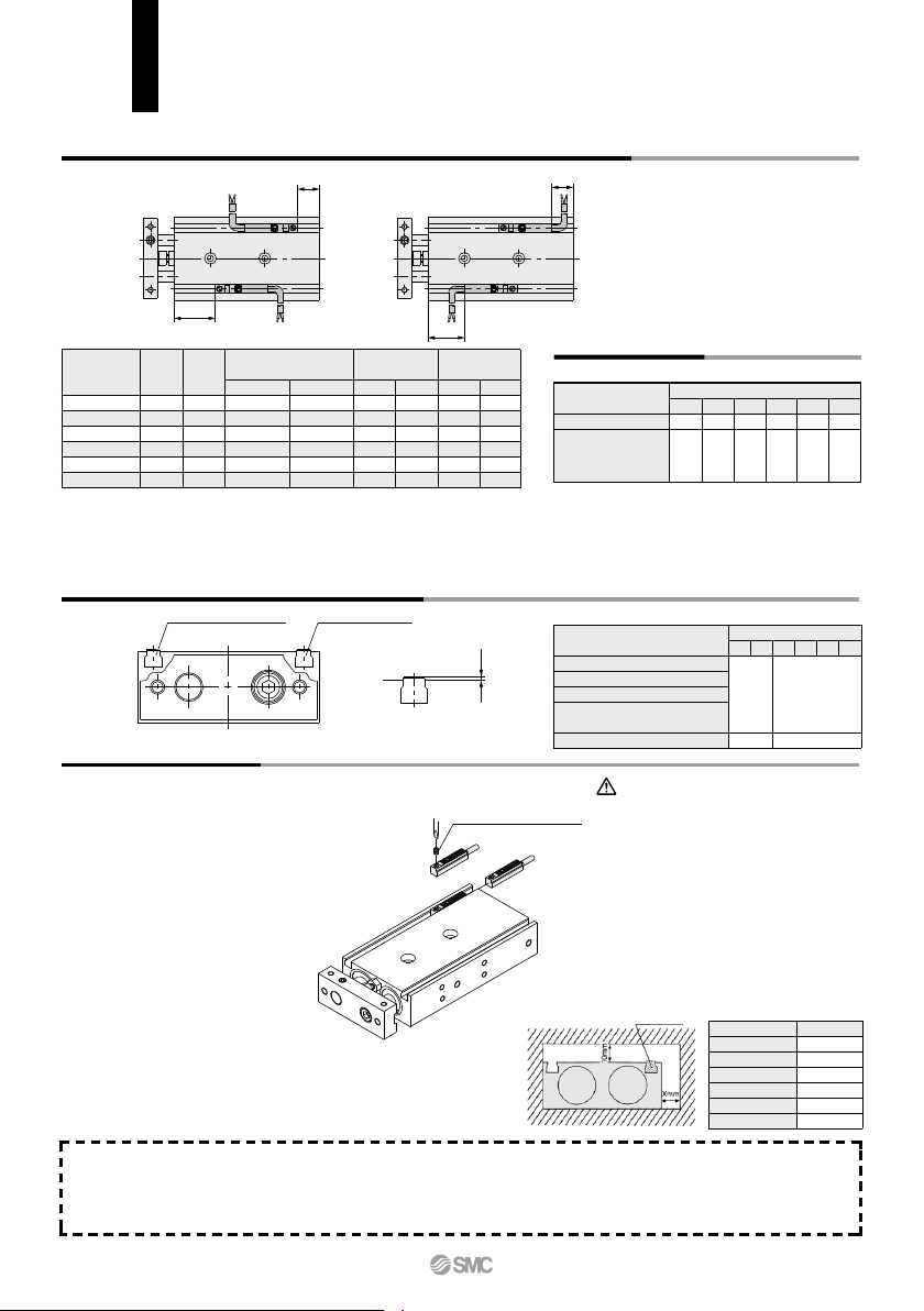
Auto Switch Proper Mounting Position (Detection at Stroke End)
Electrical entry direction:
Inward
Electrical entry direction:
Outward
Operating Range
Dimensions for Mounting of Auto Switch
Auto Switch Mounting
Other than the applicable auto switches listed in “How to Order”, the following auto switches can be mounted.
For detailed specifications, refer to pages 1119 to 1245.
CXS Series
Auto Switch Mounting
6
10
15
20
25
32
Bore size
(mm)
15.5
22.5
30.5
38
38
48
A
C
11.5 (10)
18.5 (17)
26.5 (25)
34 (32.5)
34 (32.5)
44 (42.5)
D
0.5 (–1)
3.5 (2)
0.5 (–1)
3 (1.5)
5 (3.5)
5 (3.5)
C
13
20
28
36
36
46
C
5.5
12.5
20.5
28
28
38
D
4.5
7.5
4.5
7
9
9
B
D-Z7/Z8, D-Y7W
D-Y5, D-Y7
D-Y6, D-Y7V
D-Y7WV
D-Y7BA
Note 1) Negative figures in the table D indicate how much the load wires protrude from the cylin-
der body.
Note 2) ( ): Denotes the dimensions of D-Z73.
Note 3) Adjust the auto switch after confirming the operating conditions in the actual setting.
–5.5
–2.5
–5.5
–3
–1
–1
D
2
5
2
4.5
6.5
6.5
D-Z7/Z80
D-Y59
, D-Y69
D-Y7P/Y7PV
D-Y7W/Y7WV
D-Y7BA
Auto switch model
Bore size (mm)
6 10 15 20 25 32
9 7 9 9 9 11
3 3 3.5 3.5 4 4.5
∗ Since this is a guideline including hysteresis, not meant to
be guaranteed.
(assuming approximately ±30% dispersion.)
There may be the case it will vary substantially depending
on an ambient environment.
D-Z7, D-Z8
(Reed auto switch)
D-Y5, D-Y6, D-Y7
(Solid state auto switch)
D-Y59A/Y7P/Y59B
D-Y69A/Y7PV/Y69B
D-Y7NWV/Y7PWV/Y7BWV
D-Y7NW/Y7PW/Y7BW
D-Y7BA
D-Z7, D-Z8
Bore size (mm)
A Dimension
Auto switch model
When mounting and securing auto switches, they
should be inserted into the cylinder’s auto switch
mounting rail from the direction shown in the drawing
below.
After setting in the mounting position, use a flat head
watchmaker's screwdriver to tighten the auto switch
mounting screw that is included.
When tightening an auto switch mounting
screw, use a watchmakers’ screwdriver with a
handle of approximately 5 to 6 mm in diameter.
Also, tighten with a torque of about 0.05 to 0.1
N·m. As a guide, turn about 90° past the point at
which tightening can first be felt.
Note)
Auto switch mounting screw
M2.5 x 4 L
(Included with auto switch)
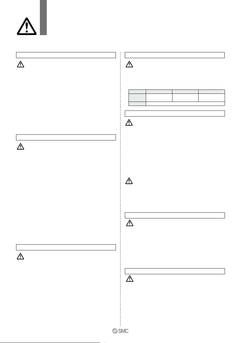
1. Avoid proximity to magnetic objects
When magnetic substances such as iron
(including flange brackets) are in close
proximity to a cylinder body with an auto
switch, be sure to provide a clearance
between the magnetic substance and the
cylinder body as shown in the drawing below.
If the clearance is less than the values noted
in the table below, the auto switch may not
function properly.
Caution
Auto switch
Bore size
0
0
10
10
0
0
ø6
ø10
ø15
ø20
ø25
ø32
X (mm)
758
A
Without Plate
1
This specification is for the cylinder without a plate. This cylinder is suitable for mounting your own plate.
Please note that the rod end dimensions of this cylinder are different from those of the standard cylinder.
CXS X593
Bore size
Without plate
Stroke Auto switch
B
A A
B
C
O
View C
Section A-A
Section B-B
C
a
s
b
d
e
f g
C0.2
C0.2
C0.5
45
°
45°
i
h
L1
k
m
45
°
p
n
(d)
q
C0.5
C0.5
t
j
r
(L1)
a
16
±
0.1
20
±
0.1
25
±
0.1
28
±
0.1
35
±
0.1
44
±
0.1
b
ø4
ø6
ø8
ø10
ø12
ø16
+0.019
+0.001
+0.019
+0.001
c
M3 x 0.5
M5 x 0.8
M6 x 1.0
M8 x 1.25
M8 x 1.25
M10 x 1.5
d
ø4
ø6
ø8
ø10
ø12
ø16
e
ø3.5
ø5.5
ø7.5
ø9.5
ø11.5
ø15.5
f
1
1.25
2
2
2
3.5
g
3
4.5
5
7
7
8
j
2.75
4
5
6
6
8
h
ø5.5
ø6.5
ø9.5
ø11
ø11
ø14
i o
M2.5 x 0.45
M3 x 0.5
M5 x 0.8
M6 x 1.0
M6 x 1.0
M8 x 1.25
q
4.5
8
8
10
12
12.5
p
3
r
3.5
5
7
8
8.5
11
s
4.75
6.5
8
9.5
9.5
13.5
ø6
ø3.5
ø5.5
ø6.6
ø6.6
ø9
0
–0.2
0
–0.2
0
–0.2
0
–0.2
0
–0.2
0
–0.2
k
2.8
3.2
5.2
6.2
6.2
8.2
+0.2
0
+0.2
0
+0.3
0
+0.3
0
+0.3
0
+0.4
0
n
3.5
5
6
8
10
13
–0.05
–0.15
–0.05
–0.15
–0.05
–0.15
–0.05
–0.15
–0.05
–0.15
–0.05
–0.15
m
0.5
1
1.5
2
2
2
+0.2
0
+0.2
0
+0.2
0
+0.2
0
+0.2
0
+0.2
0
L1
3.5
5
6
8
10
13
+0.1
0
+0.1
0
+0.2
0
+0.2
0
+0.2
0
+0.2
0
Model
CXS10
CXS
6
CXS
15
CXS
20
CXS
25
CXS
32
+0.016
+0.001
+0.013
+0.001
+0.016
+0.001
+0.016
+0.001
t
C0.5
C0.5
C0.5
C0.5
C0.7
C0.7
(mm)
-X593
Symbol
Note 1) Unless indicated otherwise, the dimensional tolerance conforms to the ordinary dimensional difference (matching) per JIS B 0405.
Note 2) Piston rod A and B must be extended in order to install a plate. Apply presure (0.2 MPa or more) from the supply port of the extended end when installing a plate.
To secure the plate to the rods, attach it first to piston rod B, and then to piston rod A. Make sure to apply Loctite to the threaded portion.
After anchoring the plate, operate the cylinder to check for proper operation (e.g., the cylinder operates smoothly when moved by hand or at least operates properly at the
minimum operating pressure).
CXS Series
Made to Order: Individual Specifications
Please contact SMC for detailed dimensions, specifications and lead times.
759
CX2
CXW
CXT
CXSJ
CXS
D-
-X
CXS
Operating Environment
Speed Adjustment
CXS Series
Specific Product Precautions
Be sure to read this before handling the products.
Refer to back page 50 for Safety Instructions and pages 3 to 12 for Actuator and
Auto Switch Precautions.
Mounting
Caution
Caution
Caution
1. Make sure that the surface on which the cylinder is
to be mounted is flat (reference value for flatness:
0.05 or less).
Dual rod cylinders can be mounted from 3 directions,
however, make sure that the surface on which the cylinder is
to be mounted is flat (reference value for flatness: 0.05 or
less). Otherwise, the accuracy of the piston rod operation is
not achieved, and malfunctioning can occur.
2. Piston rod must be retracted when mounting the
cylinder.
Scratches or gouges in the piston rod may lead to damaged
bearings and seals and cause malfunctions or air leakage.
Caution
Caution
Caution
1. After adjusting the stroke, make sure to tighten the
hexagon nut to prevent it from loosening.
Dual rod cylinders have a bolt to adjust 0 to –5 mm strokes on
the retracted end (IN).
Loosen the hexagon nut to adjust the stroke; however, make
sure to tighten the hexagon nut after making an adjustment.
2.
Never operate a cylinder with its bumper bolt removed.
Also, do not attempt to tighten the bumper bolt
without using a nut.
If the bumper bolt is removed, the piston hits the head cover
causing damage to the cylinder. Therefore, do not use a
cylinder without a bumper bolt.
Furthermore, if the bumper bolt is tightened without a nut, the
piston seal is caught in the leveled part, damaging the seal.
Stroke Adjustment
Stroke Adjustment
3.
A bumper at the end of the bumper bolt is replaceable.
In case a missing bumper, or a bumper has a permanent
settling, use following part numbers for ordering.
Bore size (mm)
Part no.
Qty.
6, 10, 15
CXS10-34A
28747
20, 25
CXS20-34A
28749
1
32
CXS32-34A
28751
Disassembly and Maintenance
1. Never use a cylinder with its plate removed.
When removing the hexagon socket head cap screw on the
end plate, the piston rod must be secured to prevent from
rotating. However, if the sliding parts of the piston rod are
scratched and gouged, a malfunction may occur. If the plate is
not required for your application, use the cylinder that does not
come with a plate, available through made-to-order (-X593) on
page 759.
2. When disassembling and reassembling the cylinder,
please contact SMC or refer to the separate operation
manual.
1.
Do not operate the cylinder in a pressurized environment.
The pressurized air may flow inside the cylinder due to its
construction.
2.
Do not use as a stopper. This may cause malfunction.
When using as a stopper, select a stopper cylinder
(RS series) or a compact guide cylinder (MGP series).
1. A sudden extension may occur with CXS6.
CXS6 has a low internal volume and sudden extension/erratic
movement may occur particularly when it is used at low speed.
This sudden extension can be mitigated by combining the use
of meter-in and meter-out speed controllers.
Warning
1. Take precautions when your hands are near the
plate and housing.
Take sufficient care to avoid getting your hands or fingers
caught when the cylinder is operated.
Caution
1. Plug the appropriate supply port(s) according to the
operating conditions.
Dual-rod cylinders have 2 supply ports for each operating
direction (3 supply ports for ø6 only). Plug the appropriate
supply port according to the operating conditions. When
changing the port position, use the removed plug or a new
plug. If reusing the removed plug, apply sealant, etc., before
reassembly. If using a new M5 plug, apply a thin layer of
grease all the way around the male thread before use. In
addition, clear any foreign matter adhered to the port the plug
was removed from before piping.
After reassembly, be sure to check for air leakage before
operating the product.
Piping
(ø6)CXS10-08-28747B
(ø10 to ø20)CXS20-08-28749A
(ø25 to ø32)CYP025-08B29449(Rc 1/8)
CXS25-08-A3025A(NPT 1/8)
CXS25-08-A3911(G 1/8)
Plug part no.:
760
c