6-2-2-p0723-0782-cxsj_en.pdf - 第27页
Watchmaker’s screwdriver Auto switch mounting screw Auto switch • Use a watchmaker’s screwdriver with a handle 5 to 6 mm in diameter when tightening the au to switch mounting screw. Auto Switch Mounting 10 mm 10 mm Tight…
C
D
A
B
D-A9
(Reed switch)
D-M9W
D-M9
D-M9A
(Solid state switch)
D-M9V
D-M9WV
D-M9AV
(Solid state switch)
D
1
D
2
C
2
C1
C3
B
1
A1
A
B
C
D
D-A9 (Reed switch)
D-M9 (Solid state switch)
D-M9W
D-M9A
D-A9V (Reed switch)
D-M9V (Solid state switch)
D-M9WV
D-M9AV
A
1
C
1
C3
C2
Electrical entry direction:
Inward
Electrical entry direction:
Outward
D-A9V
(Reed switch)
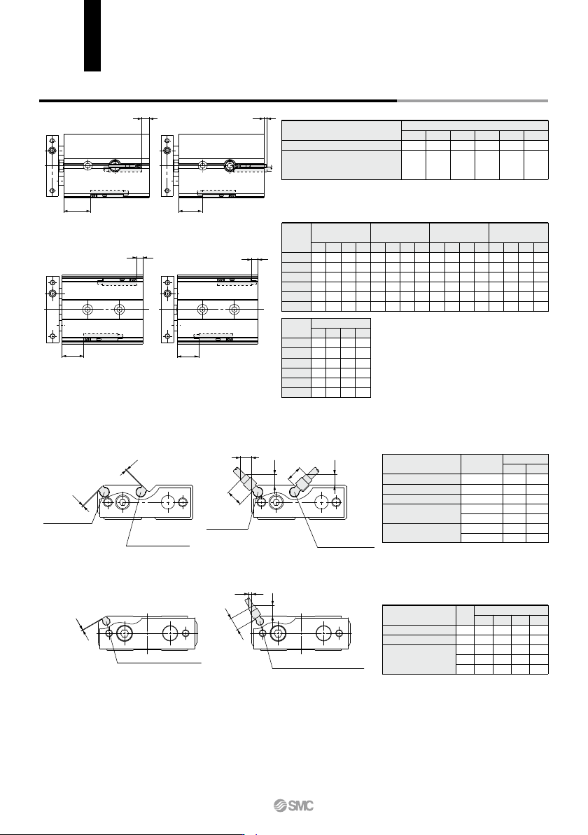
CXSJ6, 10
CXSJ6,10
CXSJ15 to 32
CXSJ15 to 32
Auto switch mounting dimensions
Symbol
A1
A1
C1
C2
C3
15 20 25
1
2
5.5
4.5
1
1
2
5.5
4.5
—
1
2
5.5
4.5
—
1
2
5.5
4.5
—
32
D-M9, D-M9W
D-M9A
D-A9V
D-M9WV
D-M9AV
Auto switch model
(mm)
(mm)
D-A9, D-A9V
D-M9, D-M9V
D-M9A, D-M9AV
D-M9W, D-M9WV
Auto switch model
Bore size
Operating Range
Auto Switch Proper Mounting Position
6
5
2.5
10
6
3
15
6
3.5
20
7.5
4.5
25
8
4.5
32
9
5
A
15.5
25.5
31.5
39
40
49
B
—
—
6
9
11
11.5
C
13.5
23.5
29.5
37
38
47
D
5.5
3
4
7
9
9.5
A
15.5
25.5
31.5
39
40
49
B
—
—
6
9
11
11.5
C
11
21
27
34.5
35.5
44.5
D
8
5.5
1.5
4.5
6.5
7
A
19.5
29.5
35.5
43
44
53
B
0.5
3
10
13
15
15.5
C
9.5
19.5
25.5
33
34
43
D
9.5
7
0
3
5
5.5
6
10
15
20
25
32
Bore size
(mm)
D-M9
, D-M9
W
D-M9
AV
D-A93D-A90, D-A96
A
19.5
29.5
35.5
43
44
53
B
0.5
3
10
13
15
15.5
C
7.5
17.5
23.5
31
32
41
D
11.5
9
2
5
7
7.5
6
10
15
20
25
32
Bore size
(mm)
D-M9A
A
19.5
29.5
35.5
43
44
53
B
0.5
3
10
13
15
15.5
C
11.5
21.5
27.5
35
36
45
D
7.5
5
2
5
7
7.5
D-M9V, D-M9WV
Bore size
∗ The operating ranges are provided as guidelines including hystereses and are not
guaranteed values (assuming approximately ±30% variations).
They may vary significantly with ambient environments.
Symbol
A1
B1
B1
C1, D1
C2, C3, D2
C1, D1
C2, C3, D2
6
1
1
2
5.5
4
8
6
1
1
2
5.5
4
8
6
10
Bore size
D-A9
D-M9,
D-M9W
D-M9A
D-A9V
D-M9V, D-M9WV
D-M9AV
Auto switch model
(mm)
Auto Switch Proper Mounting Position for Stroke End Detection
Note 1) ø6: D-A90, A96, A93, F9BA
ø10: D-A90, A96, A93
Only outward electrical entry (D dimen-
sion) is available.
Note 2) Minus value in D column (ø15, ø20, ø25,
ø32) means that the auto switches are to
be mounted beyond the cylinder body
edges.
Note 3) When setting an auto switch, confirm the
operation and adjust its mounting position.
CXSJ Series
Auto Switch Mounting
746
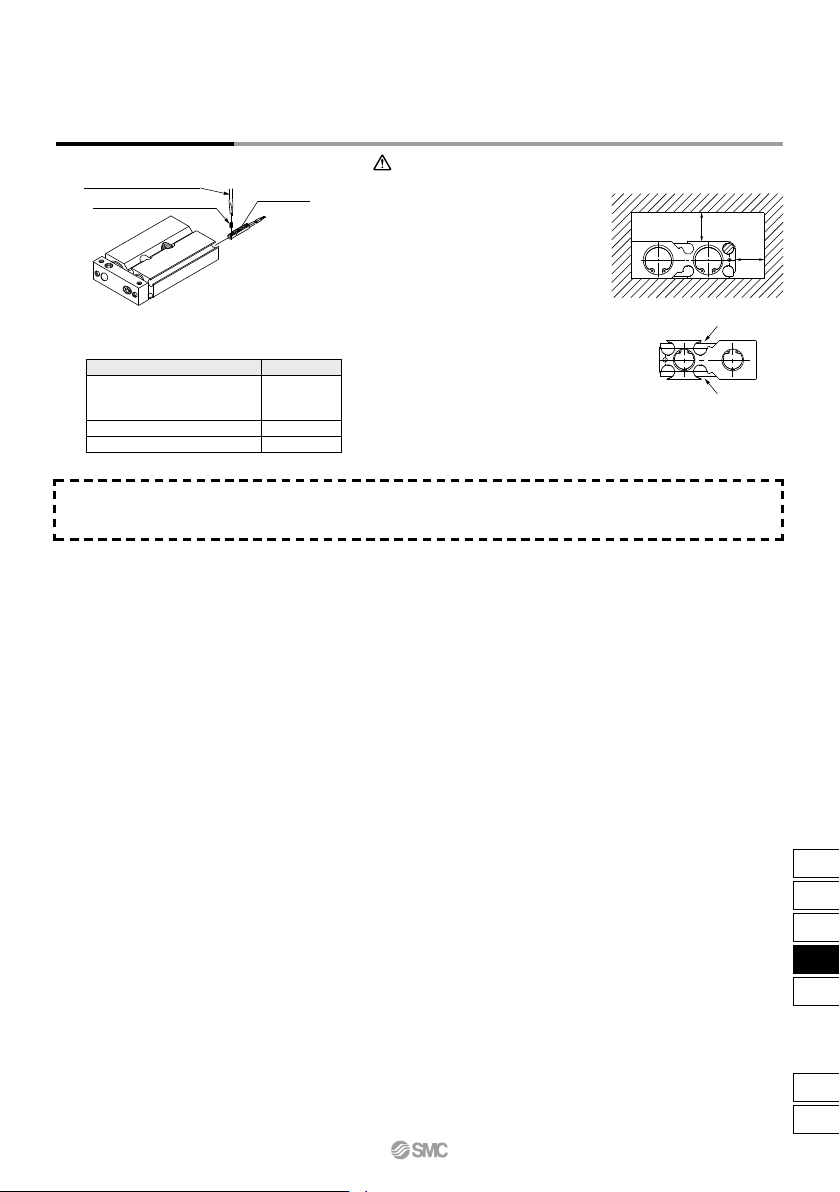
Watchmaker’s screwdriver
Auto switch mounting screw
Auto switch
• Use a watchmaker’s screwdriver with
a handle 5 to 6 mm in diameter when
tightening the auto switch mounting
screw.
Auto Switch Mounting
10 mm
10 mm
Tightening Torque of Auto Switch Mounting Screw
(N·m)
q Avoid proximity to magnetic objects.
When magnetic substances such as iron
(including flange brackets) are in close
proximity to an auto switch cylinder (auto
switch mounting side), be sure to provide a
clearance between the magnetic substance
and the cylinder body as shown in the
drawing below. If the clearance is less than
10 mm, the auto switch may not function
properly.
w For CXSJ6/10, the switch cannot be
attached or detached from the plate
side if the middle groove (indicated
by arrows in the figure on the right) is
used. (It will interfere with the bumper
bolt at the end of the groove.)
Caution
Other than the applicable auto switches listed in “How to Order,” the following auto switches can be mounted.
∗ Normally closed (NC = b contact) solid state auto switches (D-M9E(V)) are also available. For details, refer to page 1592-1.
Auto Switch Mounting CXSJ Series
D-M9(V)
D-M9W(V)
D-A93
D-M9A(V)
D-A9(V) (Excludes the D-A93)
Auto switch model Tightening torque
0.05 to 0.15
0.05 to 0.10
0.10 to 0.20
747
CX2
CXW
CXT
CXSJ
CXS
D-
-X
CXSJ
B
A
A
Section A
–
A
Bolt holder (movable)
B
B
Section B
–
B
Approx. 0.5 or less
L2
L1
Bore size (mm)
Part no.
Qty.
6, 10, 15
CXS10-34A
28747
20, 25
CXS20-34A
28749
1
32
CXS32-34A
28751
CXSJ Series
Specific Product Precautions
Be sure to read this before handling the products.
Refer to back page 50 for Safety Instructions and pages 3 to 12 for Actuator and
Auto Switch Precautions.
1. Make sure that the surface on which the cylinder is
to be mounted is flat (reference value for flatness:
0.05 or less).
Dual-rod cylinders can be mounted from 3 directions, however,
make sure that the surface on which the cylinder is to be
mounted is flat (reference value for flatness: 0.05 or less).
Otherwise, the accuracy of the piston rod operation is not
achieved, and malfunctioning can occur.
2. The piston rod must be retracted when mounting
the cylinder.
Scratches or gouges in the piston rod may lead to damaged
bearings and seals and cause malfunctions or air leakage.
3. CXSJ (ø6, ø10)
Adjust the bolt holder using a hexagon wrench 3 mm in width
across flats so that it does not protrude from the cylinder
surface (approx. 0.5 mm depth from the cylinder surface to the
top of the holder). If the bolt holder is not properly adjusted, it
can interfere with the switch rail, hindering the auto switch
mounting. The required length of the mounting bolt for a bolt
holder and mounting hole in the rod cover side varies
depending on the bearing surface position for the mounting
bolt. Refer to dimensions L
1 and L2 provided below to select
the appropriate mounting bolt length.
Mounting
Caution
Be sure to mount the cylinder to the bolt holder. If it is oper-
ated without using the bolt holder, the bolt holder may drop.
CXSJ6
CXSJ10
L1
(mm)
5
5
L
2 (mm)
8.4
9.5
Applicable mounting bolt size
M3
M3
1.
For axial piping, the side port of the standard cylinder is
plugged. However, a plugged port can be switched according
to the operating conditions. When changing the port position,
use the removed plug or a new plug. If reusing the removed
plug, apply sealant, etc., before reassembly. If using a new M5
plug, apply a thin layer of grease all the way around the male
thread before use. In addition, clear any foreign matter
adhered to the port the plug was removed from before piping.
After reassembly, be sure to check for air leakage before
operating the product.
Plug part no.: (ø6) MTS08-08-P6830
(ø10) CXS10-08-R8601
Piping
Caution
1. After adjusting the stroke, make sure to tighten the
hexagon nut to prevent it from loosening.
Dual-rod cylinders have a bolt to adjust 0 to –5 mm strokes on
the retracted end (IN).
Loosen the hexagon nut to adjust the stroke; however, make
sure to tighten the hexagon nut after making an adjustment.
2. Never operate a cylinder with its bumper bolt re-
moved. Also, do not attempt to tighten the bumper
bolt without using a nut.
If the bumper bolt is removed, the piston hits the head cover
causing damage to the cylinder. Therefore, do not use a cylin-
der without a bumper bolt.
Furthermore, if the bumper bolt is tightened without a nut, the
piston seal is caught in the leveled part, damaging the seal.
3. A bumper at the end of the bumper bolt is replace-
able.
In case of a missing bumper, or a bumper has a permanent
settling, use the
right part
numbers for
ordering.
Stroke Adjustment
Caution
1. Never use a cylinder with its plate removed.
When removing the hexagon socket head cap screw on the
end plate, the piston rod must be secured to prevent from ro-
tating. However, if the sliding parts of the piston rod are
scratched and gouged, a malfunction may occur.
2.
When disassembling and reassembling the cylinder,
contact SMC or refer to the separate operation manual.
Disassembly and Maintenance
1. Take precautions when your hands are near the
plate and housing.
When the cylinder is operated, take extra precautions to avoid
getting your hands and fingers caught between the plate and
housing, that can cause a bodily injury.
Warning
Caution
1.
Do not operate the cylinder in a pressurized environment.
The pressurized air may flow inside the cylinder due to its construction.
2.
Do not use as a stopper. This may cause malfunction.
When using as a stopper, select a stopper cylinder (RS
series) or a compact guide cylinder (MGP series).
Operating Environment
Caution
1. A sudden extension may occur with CXSJ6.
CXSJ6 has a low internal volume and sudden extension/erratic
movement may occur particularly when it is used at low speed.
This sudden extension can be mitigated by combining the use of
meter-in and meter-out speed controllers.
Speed Adjustment
Caution
748
c